- Details
Tesla Drive Unit Photo Fitting
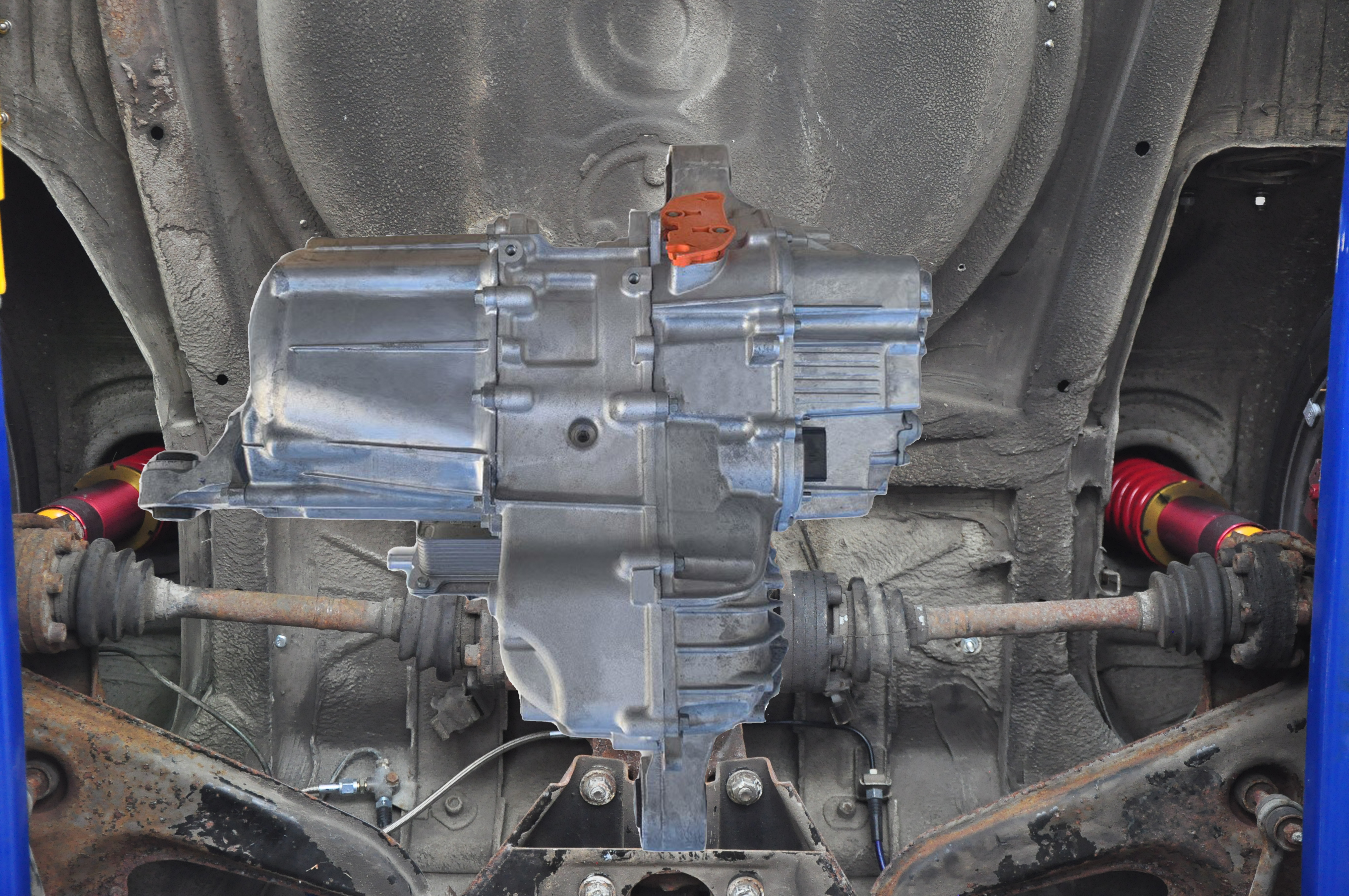
The biggest unknowns about using a Tesla drive unit is how it will fit and how it will attach to the car. Since I am a photographer and I know how to use photoshop I made a photographic fitting of the Tesla small rear drive unit to my car. First, I took some pictures of the bottom of my car directly below the differential. I then made some measurements so I could scale the photographs. The distance from the end of the axle carrier to the side of the spare tire well is 21”. The Tesla small rear drive unit is 22” between the mounting points. So, it seems there is room to fit the Tesla drive unit. But the most important alignment is that the center of the drive section must be at the center of the output shafts. I grabbed a screen capture of a Tesla small rear drive unit and brought that image into photoshop and embedded it in the image of the bottom of car. I adjusted the size of the Tesla unit so it matched the scale of the photo. From this exercise the Tesla drive unit will fit with the drive section aligned to the output shafts. Toward the front of the car a simple mount can be used to bolt the Tesla drive unit to the axle carrier once the differential is removed. But the image shown below indicates that the other end of the Tesla drive unit mounting will have to be inside the spare tire wheel well. That will actually work out well as there are frame rails on each side of the spare tire well to tie a support structure for the Tesla drive unit. The mount that is on the left side of the motor in the photo can be changed to also tie into the frame rails. My Brusa battery pack charger is the only thing in the spare tire well and that can be located to somewhere else in the trunk because some of the batteries in the trunk will most likely be moved to the engine compartment. Other components that might have to move to the trunk are the DC/DC converter and the primary bus connection. The design of the car currently is engine compartment centric. That will all have to move to the trunk because the drive unit will be in rear of the car. The water cooling required for the Tesla unit will be another complication. The reservoirs/ pumps and cooling fan/radiator are in the front of the car. I will have to determine if pumping coolant from the front of the car to the back makes sense. A quick calculation of weight indicates one or two batteries will need to reside in the trunk. The other three will go in the engine compartment in a new battery box that will have to be designed to be weatherproof. The placement of the batteries will depend on the weight distribution once the Siemens motor, 5-speed transmission, driveshaft and rear differential are removed and the Tesla drive unit installed.
- Details
Rinehart No-Go, Tesla Drive Unit, Yes-Yes
I have decided not to return the Rinehart for evaluation and repair. I am worried that the repair could be as much as a new unit. Even if the repair was a fraction of new unit and they test the system before returning it to me, there is no guarantee that it will work in my car. It is odd that I have had two other inverters in the car and they both worked, after initial startup issues. But I worked continuously on setting up the Rinehart for over two months and could only get it to enable, but not turn the wheels. I would rather have a new unit than one that was repaired because they will have only repaired the failed components and their tests might not reveal what the issue was that caused it to fail in my car. I have said to people that if I was doing a conversion today that I would put a Tesla drive unit in it. Used Tesla drive units have been steadily coming down in price as the number of Tesla cars are on the road and consequently the number of wrecked Teslas. The Tesla drive unit is complete package, motor, inverter and output drive. Just a controller and appropriate accelerator and brake pedals are needed. The biggest unknown for putting a Tesla drive unit in the 320e is rear drive structure strong enough for the doubling in torque and nearly tripling in horsepower a small Tesla drive unit would be capable of. The Siemens/DMOC was never tested in the 320e on a dynamometer but the test vehicle for the Siemens/DMOC showed 200 ft-lb and 160HP, so the rear differential may have already seen 200 ft-lb of torque. The Tesla Drive unit would not be connected through the differential, however. In fact, the whole drive train would be removed, Siemens motor, Getrag 5-speed transmission, drive shaft and rear differential. New output shafts would have to be fabricated to fit my car. Some kind of mounting frame would also need to be fabricated to hold the Tesla. The rear axle carrier and trailing arms would have to be looked at for strength. I might see if someone could model that for me.
Add a comment- Details
Rinehart Inverter Failure
This inverter has been very much a problem from the beginning. Mechanically it was very easy to install, to get it mounted on the same mount as the Scott Drive, connected to coolant and connected to all the low and high voltage lines without any issues. But electrically and programmatically it has been problematic. First, I had to create a completely new wiring harness because the Rinehart uses Ampseal connectors and the inverter I replaced used Epic. The motor encoder control signals were also on an Ampseal connector so I had to build interface to the encoder cable that has Sealcon M23 round connectors. Even the cross-over box that I used to break out the wires had to be significantly changed and new wires had to be run for more control. I found that the inverter requires a very specific set of conditions of connections and firmware settings to be met so that it will enable the output. What makes the Rinehart great is that I had access to every firmware value that affects the opertion of the car. But that is also what makes it difficult. Even after working over the past month all the conditions still were not satisfied to enable torque output. The inverter shows that is enabled and in Run mode, but nothing happens when the accelerator is pressed. I have been getting support from Cascadia Motion and working through the issues. They discovered reviewing the output from the firmware listing is that the Hardware (HW) version had changed. That is not possible outside the factory so some transient in the system corrupted the EEPROM memory. They thought that updating the firmware may fix the inverter issues. Updating firmware in an inverter is not a new thing for me, I had to do that on both the Scott Drive and DMOC. For the Rinehart it just required the serial interface and the connection to the Software upload enable pin. I was preparing to do the firmware update, I had gotten all the connections I needed, but when I turned the car off to make the connections, I hear a loud bang and I could see the Rinehart visibly shake (I could feel it in the car too). There are no mechanical switches in the Rinehart so that noise could only be a large electrical discharge inside the unit. I tried to turn the car on, but the main contactors would not close. Those are now controlled by the Rinehart. I discovered that the 12V 5-amp fuse to the Rinehart was blown. I replaced the fuse, but when I turned the car on it blew it again. I measured the input impedance for the 12V into the Rinehart and it is several mega ohms so this is a semiconductor short – when the circuit is energized it draws too much current. I checked with the support from Cascadia Motion and they said a 10-amp fuse would be okay, but I found after a few minutes the inverter would blow that one too. It was after the 10-amp fuse blew that I could smell the familiar smell of burnt electronics. So now the Rinehart is probably bricked. Cascadia Motion does have an RMA and repair service. They charge $650 to evaluate the unit and give you a quote for repair. The problem will be what actually failed. Was it just the controller board or did one or more of the IGBT transistors blow too? Something had a large electrical breakdown to make the unit move and create that loud bang. I requested and received an RMA, but I will have to think about if I even want to know what went wrong. If it is something major the repair could be as much as a new unit. That unit won’t even turn on with is not promising and the $650 could be just a waste of money. I removed the inverter from the car, it had to be cleaned of cooling fluid and the inlets capped, in case I decide to send it back to Cascadia Motion. While I had It out, I put it on my test bench. With a DC power supply that was only 40W I was able to turn the inverter on. It drew more current when it started up and pulled the voltage down on the supply but that only lasted a second or two. When it settled it was only drawing 650mA. I was able to connect to it with the RS-232 and using their GUI I found that it now showed multiple hardware failures. And the HW version had changed again. I took a screen shot of that and sent it off to Cascadia Motion support. From those faults they said it’s most likely the power module (IGBT), potentially the gate drive board too, but not the control card and not likely the IO board. The repair could be somewhere between about $1500-$2500, but I would know without sending the unit back. The timing is also an issue. The RMA request said that process of evaluation my take 4 - 6 weeks and the repair could be twice that, even longer if they do not have the spare parts. Since the Rinehart is now removed from the car I went ahead and put the Scott Drive back in because I would like to drive the car now the seasons have changed. I had retained the wiring harness and mechanically did not alter the engine bay so it dropped right in. I did not even change the cooling lines. I had bought all new hardware because Rinehart uses AN fittings and the Scott Drive is barb hose fittings, but I never got a chance to change the fittings. The Scott Drive uses many fewer inputs than the Rinehart so it only took a day to rewire the cross-over box. I started up the Scott Drive and run the Scott Drive GUI. The throttle and brake seemed to still be calibrated with the offset and gain that was in firmware and the motor spun right up when the accelerator was pressed. The regen even slowed the motor spin down with the application of the brakes. I just have to clean up the connections inside the car and then I will be able to take the 320e for a test drive. I will post another blog after I decide what I am going to do with the Rinehart.
Add a comment- Details
Rinehart Inverter PM100DX Installation
I replaced the DMOC/GEVCU inverter and controller with a Scott Drive SD100 (See Blog below Scott Drive Installation) because the GEVCU controller was having reliability issues. The Scott Drive proved to be very reliable once the setup was completed. The SD100 has many great features, including a built-in precharge circuit and isolation switch. It provides all the CAN message for the motor performance and has a GUI for setup, calibration and control. The SD100 showed much better reliability and seemed to perform well - i.e. the car seemed to accelerate well. Something that I never did for the DMOC/GEVCU setup was to run the car on a dynamometer to measure the power and torque output. The only benchmark for the DMOC/GEVCU - Siemens motor setup was in a 1978 VW Thing, that was measured to have 160HP and 221 ft-lb of torque. Last summer I found a nearby shop that had several dynamometers and was able to get the 320e tested with the Scott Drive. I was not expecting a great result as I had measured that the Scott Drive was outputting high power, but only for 3 seconds. That is hardly enough time to accelerate the car, although it is something you can definitely feel in the seat of you pants. Unfortunately, the SD100 really is not accelerating the car and was such a problem when testing on the dynamometer that in first gear the wheels would not even turn. The car would just lurch on its suspension and then settle. The Scott Drive shuts down the current to less than half of full current after 3 seconds, even with the accelerator pedal pressed to the floor. The best HP/Torque curve was obtained in 3rd gear, but is very disappointing. See the graph below.
Power torque curve for the 320e in third gear with the SD100.The max power is 128HP and the max torque only 110ft-lb.
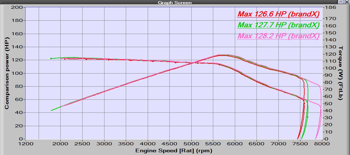
This poor power/torque performance was expected based on how the current shuts down from the inverter. There is no adjustment on that parameter, it is built into the firmware and the maker of Scott Drive does not give access to changing firmware values. I think Scott Drive does not know how to use their inverters in a car application. The only data I had seen from them was bench testing. That provides a minimal look at the performance. But it seem like their only goal is to over protect the Integrated Gate Bipolar Transistors (IGBT)s. There is no warranty on this inverter. It is more than 6 years old, so why should Scott Drive care how hard I drive the IGBTs? This issue is what convinced me to change to a Rinehart Inverter. The first parameter I looked at for the Rinehart was the current – time limit. Cascadia Motion (who own Rinehart) say in their documentation to limit the full current of 350Amp RMS to less than 30 seconds!!! Also, from the documentation is seems like most of the firmware is open – i.e., most of the parameters are adjustable. This should work much better for driving the 320e and the documentation for the Rinehart shows that Scott Drive is wrong about driving IGBTs. The small downside of the Rinehart is there is no GUI for setup and calibration. Those values all have to be entered into the firmware via a GUI that has access to every paramter, but no auto process for calibration. It is all by procedure. Below is an image of the Rinehart PM100DX inverter.
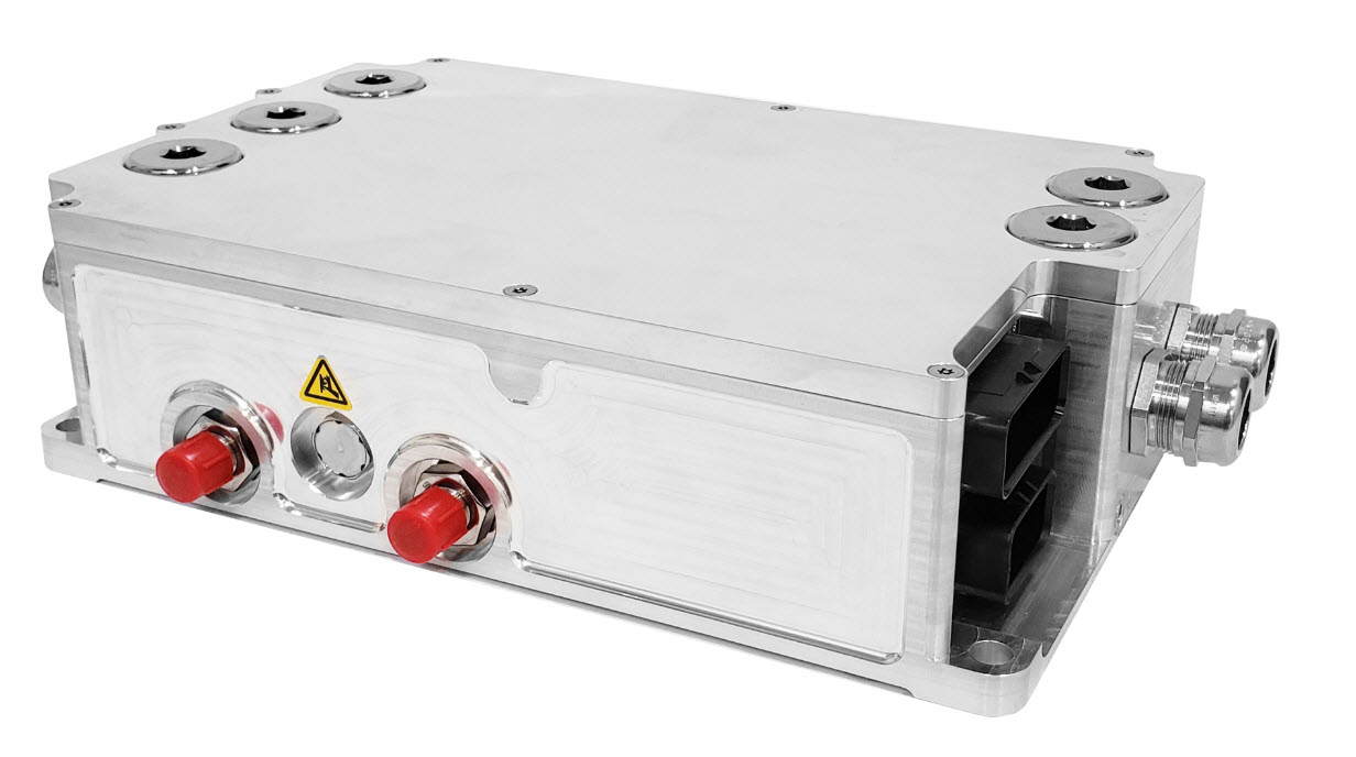
All of the high current DC and AC wires and the water lines are the same as the SD100. The biggest difference is the analog and logic connections to the controller. The PM100DX has Ampseal 35pin and Ampseal 23pin connectors for all those functions. Ampseal is actually an easier connector to work with than what was on the SD100 and most of the car uses Ampseal connectors. Because of the new connector system I had to build a whole new wiring harness and changed most of the connections in my wire crossover box. The PM100DX is a different size than the SD100 so I had to cut some aluminum plates to make an adapter to the DMOC frame, that sits on top of the Siemens motor. Because the Rinehart is considerably smaller than the SD100 I installed a couple of carbon fiber plates to cover the open areas above the Siemens Motor. Control of the Rinehart is very similar to the SD100, the major difference is the logic reference. For the SD100 logic was positive (i.e. +5V switching) but on the Rinehart the logic is ground switching. To use the same wires I already had installed in the glove box I had to verify that all the logic wires were isolated so I could just swap the connections. The only wire I had a problem with was the USB connector for phone charging. I had to grab a +12V and ground from under the dash to power that connection.
As soon as it is warm enough to drive the car (still has summer tires installed) I will schedule a session on the dynamometer and post a blog with those results.
A video of the PM100DX installation will be available soon.
Add a comment
- Details
Battery Maintenance System (BMS)
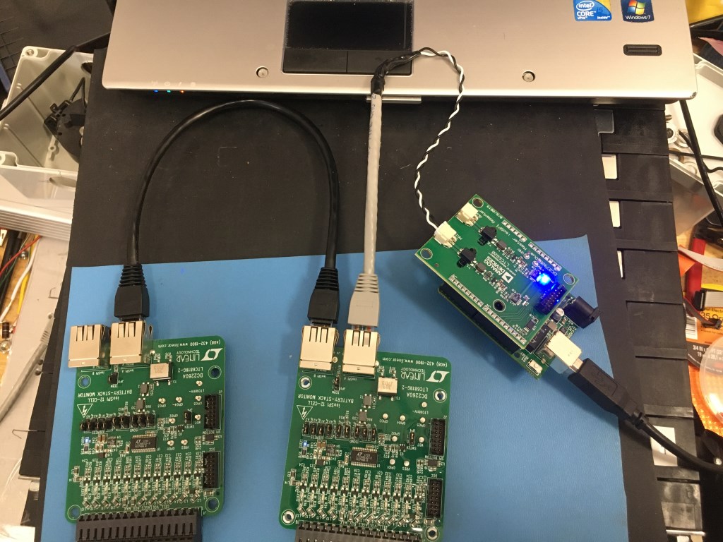
Initially the Battery Maintenance System (BMS) will be provided by the Analog Devices DC2260A BMS Demo board which demonstrates the LTC6811-2 BMS integrated circuit. This circuit has the ability to measure 12 battery cells simultaneously and communicate via either isolated SPI or standard SPI. The demo board is connected to a Linduino with a 14-pin ribbon cable. The Linduino is Analog Devices version an Arduino Uno and is required to communicate with any of the Analog Devices demo boards. Standard SPI is used to communicate between the Linduino and the demo board. If multiple BMS Demo boards are used then the isoSPI interface is used and the Linduino needs a DC2792B shield. The D2260A demo boards are somewhat expensive ($150 +S&H) plus the cost of the Linduino ($125) and DC2292B ($75) shields (9 demo boards plus 2 Linduino and 2 DC2292B would be needed). Plus an overall controlling circuit needs to be designed to take the data on the from the Linduinos on the IsoSPI connection. A new circuit based on the DC2260A has been designed and the initial build started. The new circuit design incorporates an Arduino Nano Every processor and an isolated CAN BUS interface. The Nano communicates with the LTC6811-2 to read the cell voltages and then sends that data out on the CAN BUS. A much cheaper implementation (almost one-third the price) and there already is a CAN BUS system in the car the controls the dashboard instruments. Probably the first 4 battery modules will be used with the DC2260A BMS demo boards and the other battery modules in the car will be monitored with my circuit design.
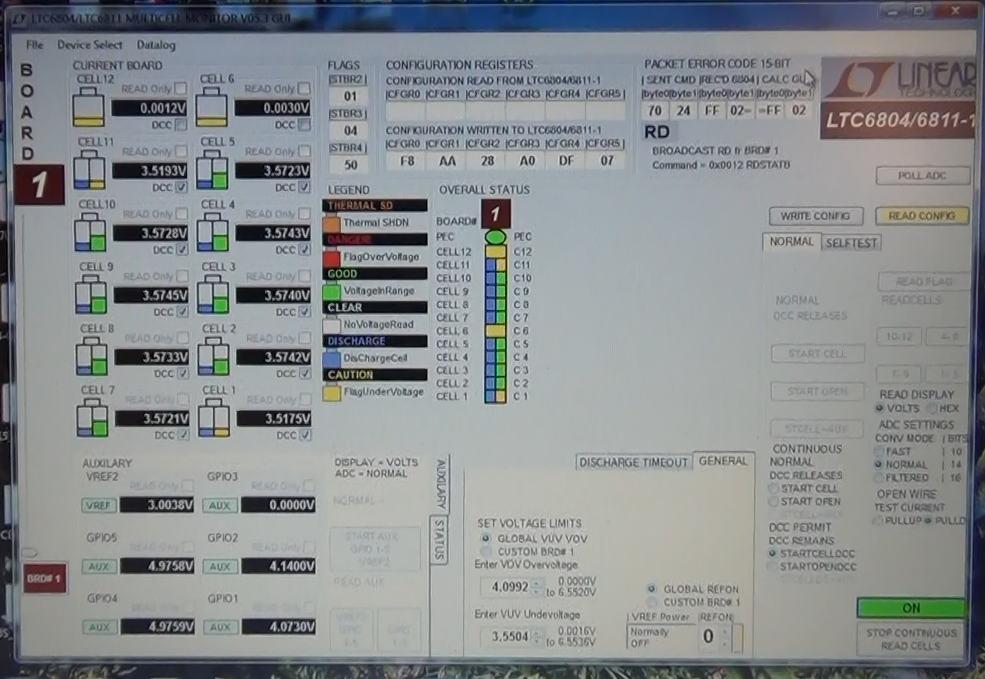
The screen picture below shows the Multicell Monitor GUI during the discharge process. In normal operation in the car, only cells that are at a higher voltage would be discharged. An algorithm will be written to control that process.
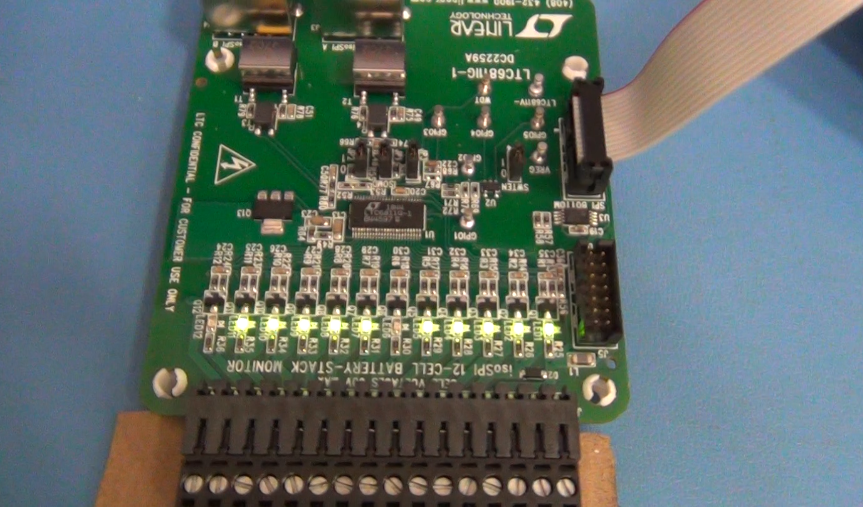
Top side of DC2259A BMS Demo board showing active discharge channels. When the MOSFETs are turned on to discharge a battery cell the LEDs light up. Again, 6 and 12 are not lit because they are not connected on the 10 cell battery module.
Bottom of DC2259A showing the discharge resistors. The resistors are 33 ohm so on a battery cell that varies from 3.5V to 4.1V there can only be a little more than 100mA discharge current. On a cell that is 180AH that would take 1800 hrs of time to fully discharge (75 days). This board is not designed for that. The design is to just trim the cell voltages so they are all the same value.
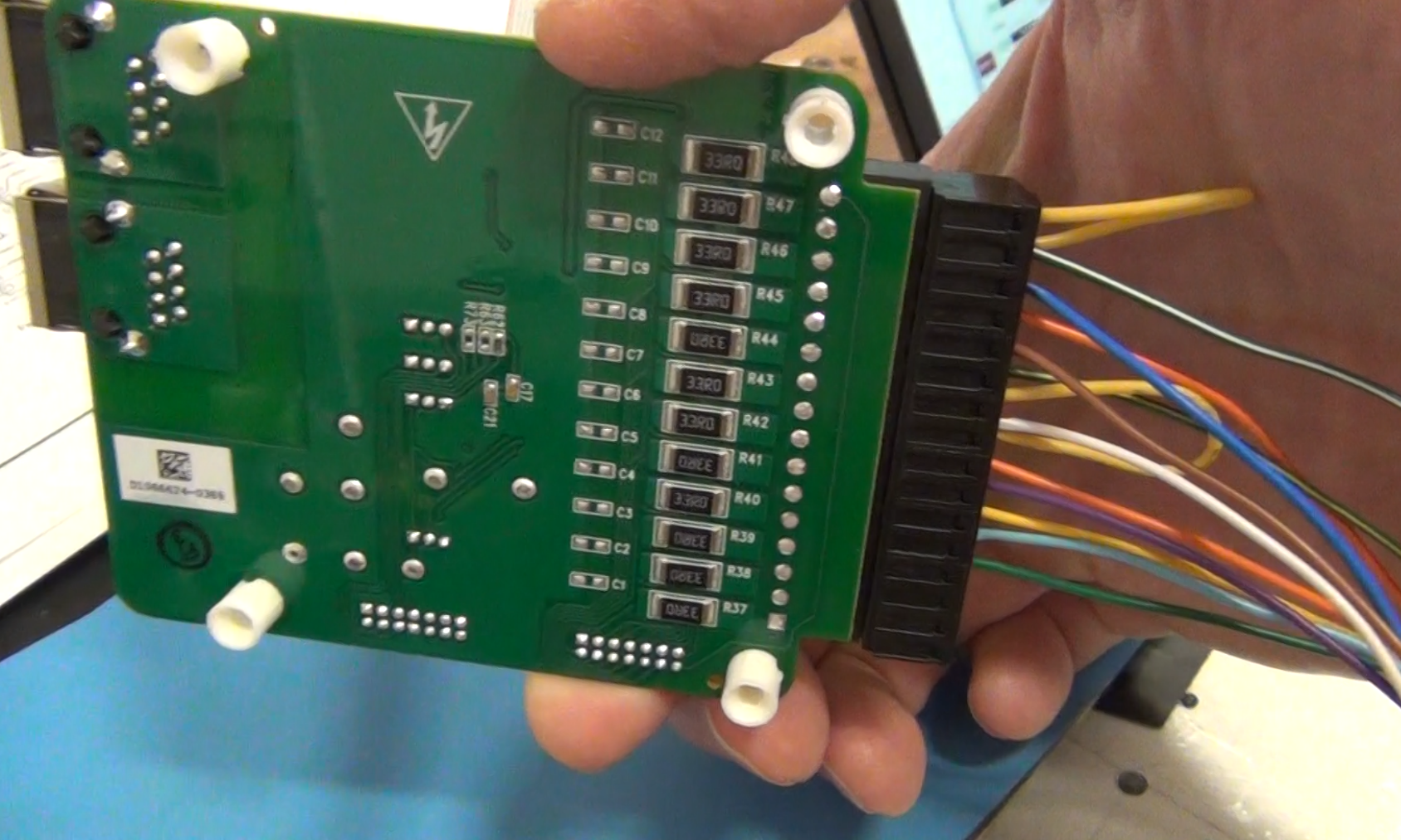
Image below shows the demonstration of the isolated SPI (isoSPI) that can be used to connect up to 5 BMS demo boards to one Linduino and a DC2792B isoSPI shield. In the car there if that system was used there will need to be two Linduino/DC2792B controllers for the 9 Bolt Battery modules. The iosSPI is limited to 5 boards so that is why it would require two Linduinos and DC2792B shields. Initially the IsoSPI will be used for the first 4 batteries and the remaining 5 will use the BMS board of my design with the isolated CAN Bus communication.