- Details
BMS Battery Temperature Measurement
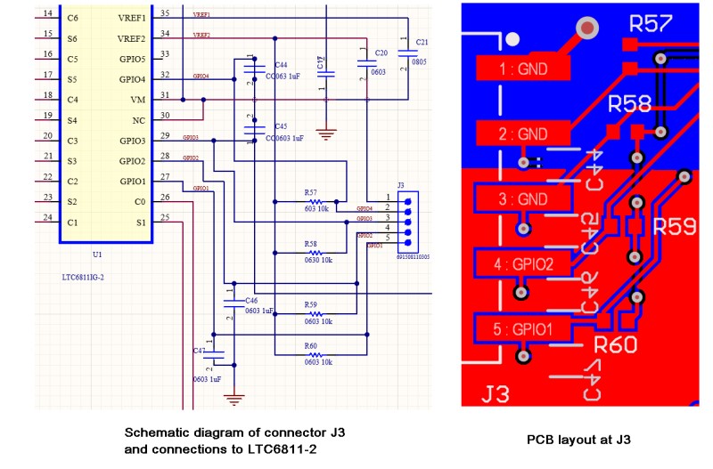
I thought I could use the four GPIO inputs on the LTC6811-2 for making temperature measurements on my battery modules. All four inputs reference the 3.3V source and the Analog Devices TMP37 work with 3.3V. However, I discovered that there is a mistake in the PCB layout that prevents me from doing that. For some reason all but the first two GPIO inputs are grounded. I reviewed the PCB layout and schematic and it appears that the changes I implemented in the schematic were not pushed to the PCB. See the image below. The schematic on the left shows all the pins on the output connector J3 are wired to the correct components and pins on the LTC6811-2. But that is not how the PCB layout looks, shown on the right. All the resistors and capacitors are there, just not the correct connections to the LTC6811-2. Unfortunately all the PCBs were fabricated with this error and all the PCAs have now been assembled.
This is a common problem I found with using the Altium CircuitMaker CAD program. Many aspects of the user interface of that program are very similar to Altium Designer, so it is easy for me to use because I was trained on Altium Designer, but because CircuitMaker is a freeware program it has a lot of bugs. Altium Designer is a $4235/year (or $355/month) program which I could only use when employed by my last job, where they had an Enterprise License. CircuitMaker is what Altium offers as a low cost solution to circuit and PCB design. I just wish they would charge something for it so it would have some technical support. With Altium Designer, tech support would usually reply within a day. Also, in Altium Designer there were many how-to demonstration videos on nearly any aspect of PCB layout and using Altium Designer. The only support for CircuitMaker is to post something in the CircuitMaker forum and then maybe a user will have a solution, but not likely. You can submit a bug report, but it does not mean the issue will be resolved. Most of the help can only be found by searching for it on the Allium site or YouTube. I also found that the layout problem is not the only issue. From a review of the documentation for the LTC6811-2 the VREF2 that is the 3.3V source can only source a few tenths of a milliamp so would it not work with multiple TMP37 sensors connected to the source. That is why in the design there are 10k resistors between the VREF2 and GPIO pins, they limit the 3.3V current. The circuit is actually designed for a NTC 10K thermistor. I tried to use that but with the GPIO pins shorted to ground it does not work to read a thermistor.
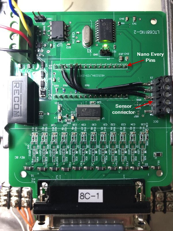
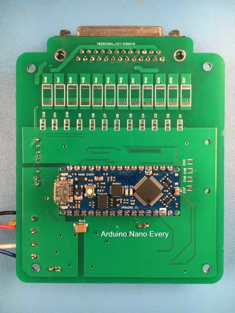
The solution I came up with is to use the analog inputs on the Arduino Nano Every, which is the controlling MCU for the BMS circuit. With the current BMS PCA design only the SPI and USB ports are used on the Nano. It has a full complement of analog, digital and PWM I/O. All the pins are available on the PCA because the Nano Every module is soldered directly to the BMS PCA and the module is on the bottom side of the PCA, so the pins protrude to the top side. Unfortunately to use the PCAs with this layout error, the traces from the pads for the the 5-pin sensor connector have to be cut to isolate them from the LTC6811-2 GPIO inputs or the ground connection. Since the connector that was chosen for the sensor connection has 5 pins I am going to just use two pins for analog input from two TMP37 sensors. One pin will be the +3.3V voltage source and one will be analog ground. This change will require three wires to be soldered to the pins on the Nano Every and to the 5-pin sensor connector pads. Using ribbon cable makes a cleaner look as shown in the image below. Once the boards are flux cleaned, I will probably put a dab of RTV silicon on the ribbon cable to stabilize it.
Add a comment
- Details
BMS Deployment
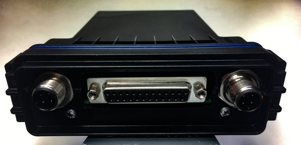
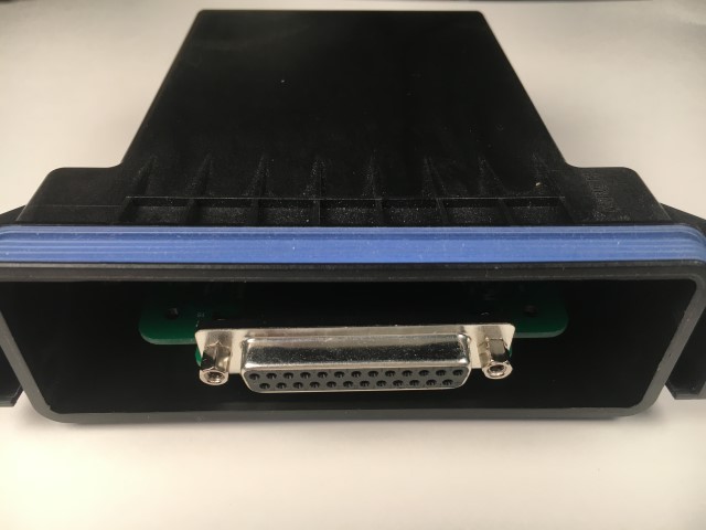
Now that I have most of the BMS PCAs completed it is time to plan for the deployment of the systems in my car. As I described below I plan top use a CINCH enclosure for the PCAs. The image below shows the enclosure with a prototype front panel. It was machined oversize to determine the best fit for the PCA in the enclosure and see how the 12mm circular connectors would fit. Now I have the measurements I can machine the front panel to fit the DB25 connector precisely. I will probably use some silicon sealer to seal the DB25 connector in the front panel to try and maintain the IP67 rating. Even though the BMS modules will be inside the car, the electronics can be affected by humidity. Originally I was planning to have two connectors with one an input and one an output and daisy-chain the BMS modules together. But I realized after I drew up the connection plan that it would mean the 12V power would be in series with each BMS. It would be better to have the 12V power connected in parallel. The CAN BUS can work either way, daisy-chained or terminated.
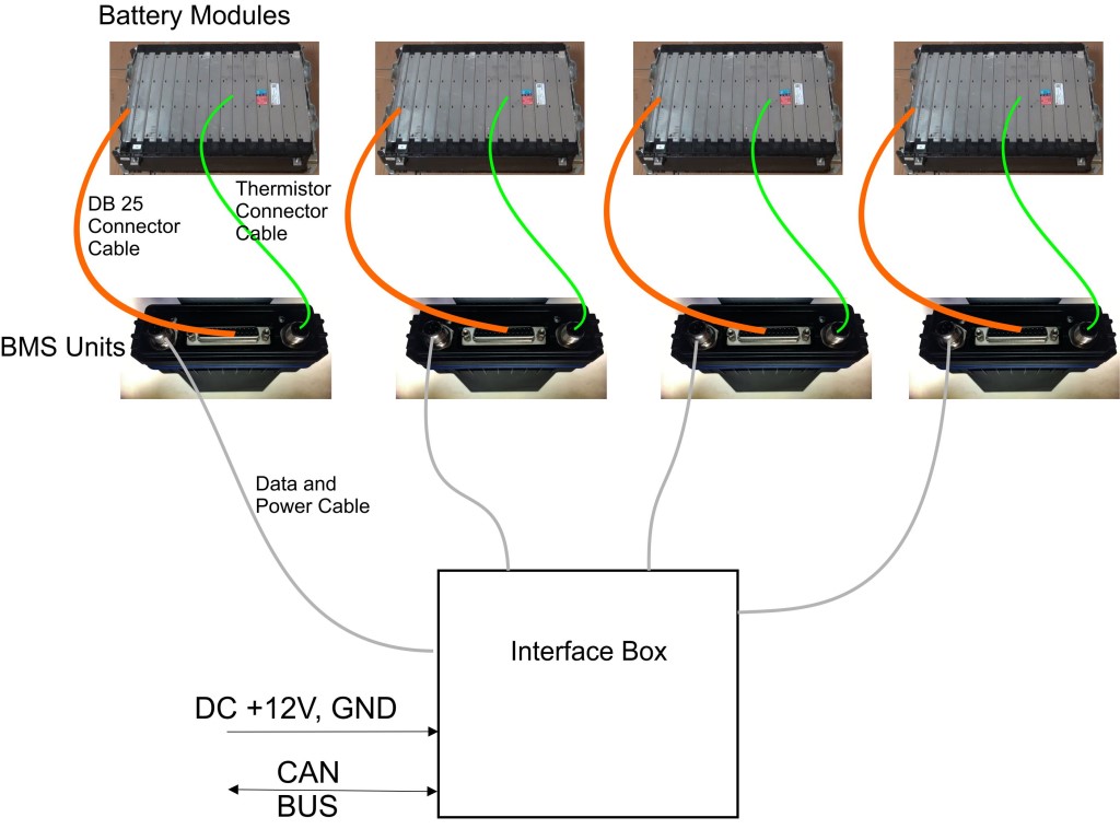
I decided to use only one 12mm 4-pin connector and have the CAN BUS be distributed to the BMS modules via the Interface Box, shown in the image below. The interface box will connect all the BMS systems together. The interface box will supply the +12V power and the CAN BUS communication and inside the box will essentially just be a busbar for the +12V and CAN BUS, no electronics required. Since I have 4 batteries under the rear seats and 4 batteries in the trunk there will be two interface boxes. The interface boxes will connect with one cable to my instrument cluster controller to read the CAN BUS. I will use the same 12mm circular connectors on the interface boxes. I ordered some 4-conductor shielded cable so now I just need to order all the 12mm connectors. After I realized that I was not going to use two connectors to connect the power and CAN BUS I was thinking it might be good to use the second connector to have a few temperature measurements of each battery. The LTC6811-2 that is the BMS integrated circuit in addition to all the battery cell inputs has 4 auxiliary inputs that could be wired to the second connector and the wires would go to a temperature sensor mounted on the battery. The code is already available in the program for the BMS to read the voltages on those auxilary inputs.
Quick Update on the Deployment: A thermistor is not going to work for temperature measurement because I do not have a Wheatstone bridge circuit to measure the thermistor resistance and hence the temperature accurately. That would require a respin of the PCB to include that circuitry. One solution for temperature measurement is to use the Analog Devices TMP37 analog temperature sensor.(Link) which is a one-wire sensor that just needs power and ground. Using this sensor I can get two temperature measurements per battery with the 4-wire cable I have. The sensor has a sensitivity of 20mV/C and a 500mV output at 25C, well within the range of the LTC6811-2.
Add a comment
- Details
BMS Bench Testing
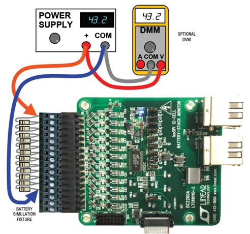
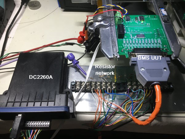
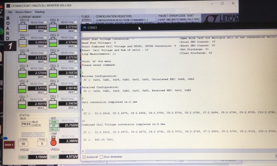
As I complete the build of each BMS PCA I have been bench testing them. When I first got the Chevy Bolt batteries and purchased the BMS demo boards, I built a resister ladder board using barrier strips and through-hole resistors. The test method was detailed in the manual for the BMS demo and is shown in the first image below. But instead of connecting resistors directly to the DC2260A BMS demo I have 10 resistors wired in series on the barrier strip to mimic the battery cells and a power supply that supplies a voltage similar to the battery stack voltage. All the resistors are the same, so nearly the same voltage drop occurs at each resistor, when a voltage is applied to the series. For my resistor series a wire is connected to each resistor and then soldered to a DB25 connector. I made this system to learn how to use the DC2260A BMS demo boards and the software when I got them two years ago. The resistor ladder is much easier to use than a battery for testing BMS boards and safer. The resistors are basically a current limiter and the power supply used to power the resistor series is current limited, so if anything shorts out it should not be catastrophic like it would be using a battery with all the current capacity. I added another set of wires and DB25 connector in parallel to the first set of wires so I could measure my BMS board and the DC2260A demo board simultaneously to compare the voltages measured. The setup is shown below and a screen capture of the simultaneous testing. As described in the Blog below (BMS Update) I have found my demo boards have an average offset of 400 microvolts from the DC2260A BMS demo board. That offset has been the same for every board I have assembled and it is the same value as the noise measured on all of the readings of +/- 0.0002V. I don’t really care about that offset, however, because I am only going to use my BMS boards as a battery monitor. The voltage readings are very reproducible and that is all that matters. Once I finish building all the BMS boards I will need to flux clean them and then conformal coat the PCAs. I will need to retest everything after those operations. Then I will ready to deploy the system in my car.
- Details
BMS Update
This is my new BMS design, based on the reference design of the Analog Devices DC2260A BMS demo board that I have been using to characterize the Bolt battery modules since I got them in 2021. (See the Blog below Battery Maintenance System (BMS) Link). The BMS demo board was great for understanding how the BMS integrated circuit, the LTC6811-2 worked. The BMS demo boards also helped me to understand more about the Bolt batteries. After using the BMS demo board I decided that I would like to have a BMS system in my car, especially since the Bolt battery module is wired for BMS connections. But the system would be more like what Tesla does where all the BMS electronics are at the battery and they communicate with a central processor. In the Chevy Bolt all 100 battery cell connections were brought to a central processing system. That required a very long and complex battery wiring harness, which I really did not want to deploy in my car. Even though the individual cells in the Bolt battery would only have a max voltage of 4.1V, the whole pack would be at 370V, which means some part of that battery wiring harness would have that high voltage on it. Running a 90 wire cable to connect my 9 battery modules together though my car is just not feasible.
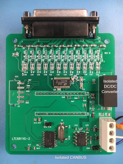
The DC2260A is a demo of a battery maintenance system. I detailed in the blog below of how the demo board has circuitry to trim the individual cell voltages. I think the greatest information I got using the DC2260A to characterize my Bolt batteries is that after nearly three years of using the batteries, with many charge and discharge cycles and no maintenance of the battery cells, the average cell voltage of 90 cells only varies +/- 1mV! (See Blog below Bolt Batteries Link)). With that kind of tight distribution and no change with many cycles it appears that the batteries do not need a battery maintenance system but rather a battery monitoring system. The DC2260A is still a great design and would work great as a battery monitoring systems so I adapted it for my car. The printed circuit board CAD files were available from Analog Devices for the BMS demo board so I used the same PCB design as the DC2260A but without the Isolated SPI (IsoSPI) circuitry. I am not populating the MOSFETs and support circuitry for the battery cell trimming. That is why there are blank pads on the PCA images below. I kept that circuit design just to future-proof my design in case I find I need battery maintenance. I detailed in the Battery Maintenance System (BMS) blog below about how the IsoSPI circuit of the DC2260A works. To use the IsoSPI requires another small PCA in addition to the DC2206A and the Linduino PCA that has to be used with the BMS demo board to measure the battery cell voltages. As I describe in that blog all those boards add up to an expensive system for the 9 battery modules in my car. That was the motivation for making my own design and building the boards. To communicate with the boards, once they are deployed on the batteries my circuit design incorporates an isolated CAN BUS circuit, instead of the IsoSPI. I already have a CAN BUS processor in my dashboard for reading the CAN BUS messages from the inverter and controlling the instrument cluster. Adding more CAN BUS frames to process is much easier than adding an IsoSPI circuit to my instrument cluster controller. The CAN BUS will only require two wires to the BMS board and they all can be connected by the same two wires because all CAN BUS communication is addressable. I also incorporated an Arduino Nano Every as the main processor. It controls and reads the LTC6811-2 IC using SPI for the cell voltages and then formats the frames and sends the data, also using SPI, to the isolated CAN BUS.
By not installing all the circuits for the battery cell voltage trimming saved money on the build. The CAN BUS integrated circuits are very inexpensive because they are used in nearly all cars now. The Arduino Nano Every is much lower cost than other micro controllers because they are very popular. Also the program that ran on the Linduino to communicate to the demo BMS is an Arduino sketch that was very easy to adapt for the different processor on the Nano Every. Most of the programming was already done to access every feature of the LTC6811-2. I was able to get samples of the LTC6811-2 IC so those were essentially free, but that will be the most expensive component if I have to buy them at $22 each. The Isolated DC/DC converter ended up the most expensive component for the first builds (at $9 each) - all total the assembled board is less than $70 each, including the cost of the LTC6811-2 IC. I built up a couple of boards and they match the commercial BMS demo board for cell measurement with only a 400 microvolt offset, that is 0.0004 V. The measurement error specified for the BMS integrated circuit is 1.2mV which is 3 times larger than what I am measuring so I am happy with my design.
The BMS board will be housed in a small CINCH enclosure shown below. The CINCH is a water-tight plastic enclosure with an IP67 rating. The enclosures were designed for automotive systems. It has structures inside the enclosure to support the PCA securely. I have blank front plates that I will machine for the DB25 connector. The DB25 connector was another improvement that I incorporated in my design. The original DC2260A has a screw terminal for connecting the battery cell connections. (See the Blog Bolt Batteries below). I put DB25 connectors on all the batteries because I had attached a DB25 to the DC2260A to make it easy to connect the demo BMS to all my battery modules. Those battery connections will now be used with my new BMS design.
Just so there is no confusion because I talk about both, I used the DC2260A and the DC2259A BMS demo boards from Analog Devices to test my batteries and to understand how the BMS IC works. The only difference in the boards is the DC2260A has the LTC6811-2 and the DC2259A has the LTC6811-1. And the only difference in these two integrated circuit is the IsoSPI, the LTC6811-2 is addressable, the LTC6811-1 is daisy chained. But since I am not using the IsoSPI it does not matter. The same code is used to control either and they are identical circuits on the battery input side which is all I am using the integrated circuit for. My CAN BUS circuit, just by the nature of CAN BUS makes my BMS boards addressable. The only advantage I can see in that is being able to load different battery trimming parameters in different battery modules. But again, I am not using that function of the IC. Just like keeping all the trimming circuitry I can use that if needed in the future. Since my BMS design is working so well I now plan to only use my BMS for the 9 battery modules. It will be easier to integrate into my car and I will not have to add any additional circuitry to my instrument cluster controller.
Add a comment
- Details
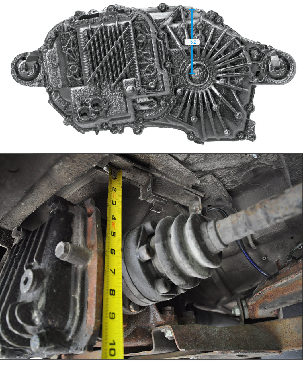
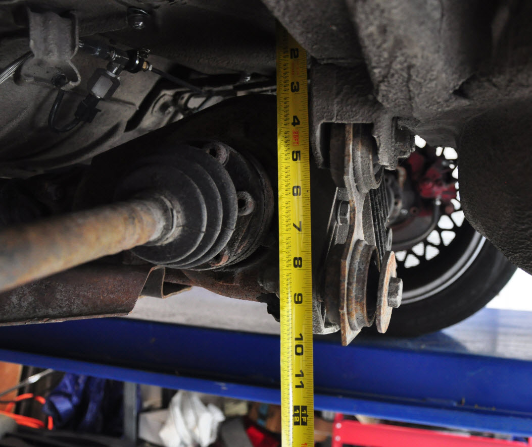
Tesla Drive Unit Measurement
The photoshop image in the blog post below looks great, but that is only from one view. The Tesla drive unit fits laterally without any issue. The more important measurement is how the unit fits in the Z direction, under the car, at the level of the output shafts. Below are two images of the measurement of the differential position from each side of the car and an image of a Test drive unit with a scale. The Tesla drive unit, in the area where the output shafts connect, is about 12” tall, with the output shafts centered in that 12”. The differential images shows that there is just clearance towards the bottom of the trunk, but when the Tesla drive output is centered on the current output shaft axis, the Tesla unit will hang nearly two more inches lower that the current differential. You can see in the lower image how far down that would hang. That could be a ground clearance issue as the car is already lowered. The only way to have the bottom of the Tesla unit at the same level as the bottom of the differential is to cut a hole in the trunk so that at least two inches of the unit would be sticking out into the trunk and the spare tire well. But there should still be enough room for two batteries and several other components like the DC/DC converter and the battery pack charger. The drive center will be above the current output shaft axis so the output shafts from the Tesla will be angled down to the wheel hubs, but the CV joints should be able to handle that small angle just like they do as for how the independent wheel suspension moves.