Chevy Bolt Batteries and BMS
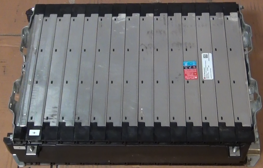
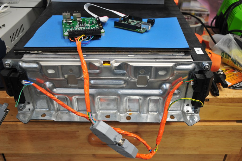
To get more driving range the batteries were upgraded in early 2021. The upgrade batteries used are the Chevy Bolt 5.94kW-h module shown in the picture below. These modules are made by LG Electronics and are NCM (Lithium Nickel Manganese Cobalt Oxide) chemistry. Each module has a 180AH capacity and the 9 modules that will be used gives a 53kW-h battery capacity. For a 85% discharge that provides 45kW-h of driving capacity. At the measured power consumption of 292W/mile by the vehicle that capacity should provide just about 155 miles driving range. A great feature of these modules is that they are already wired for a Battery Maintenance System (BMS). Each module has 10 cells and there are connections to each cell on the module. The connections are on a pair of connectors at one end of the module. The Chevy Bolt uses a central processing unit for the battery maintenance so in the Bolt each battery module has a pair of cables that runs back to the central controller. The cables with the corresponding connectors already attached were obtained form Chevy Parts Online and used to make cables to connect to a local BMS controlling circuit. Each battery module will have its own BMS controller. This is easier than running wires from each module up to the engine compartment. Although between the wires from one module the most voltage would be 42V (full charged battery) the wires will have the full pack voltage, with respect to ground. Local BMS control will be safer at this point in the 320e build. A BMS demo board, the DC2259B made by Analog Devices was initially tested to use for the module BMS. The connections to the battery module and a BMS demo board are shown in the second and third photos below. Although the new batteries are bigger and weigh more than the CALAB cells the new batteries will only increase the weight of the car 100 lbs but increase the driving range by 2 times!
BMS connection on battery module. These connectors were obtain from a Chevy Bolt battery wiring harness that was purchased online.
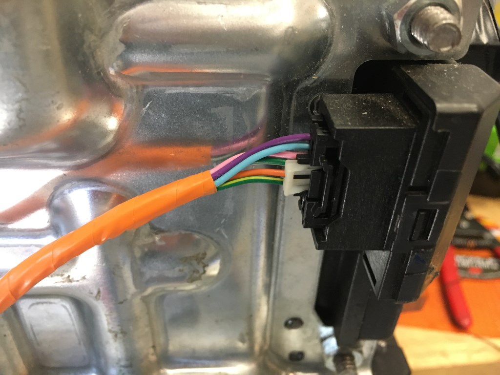
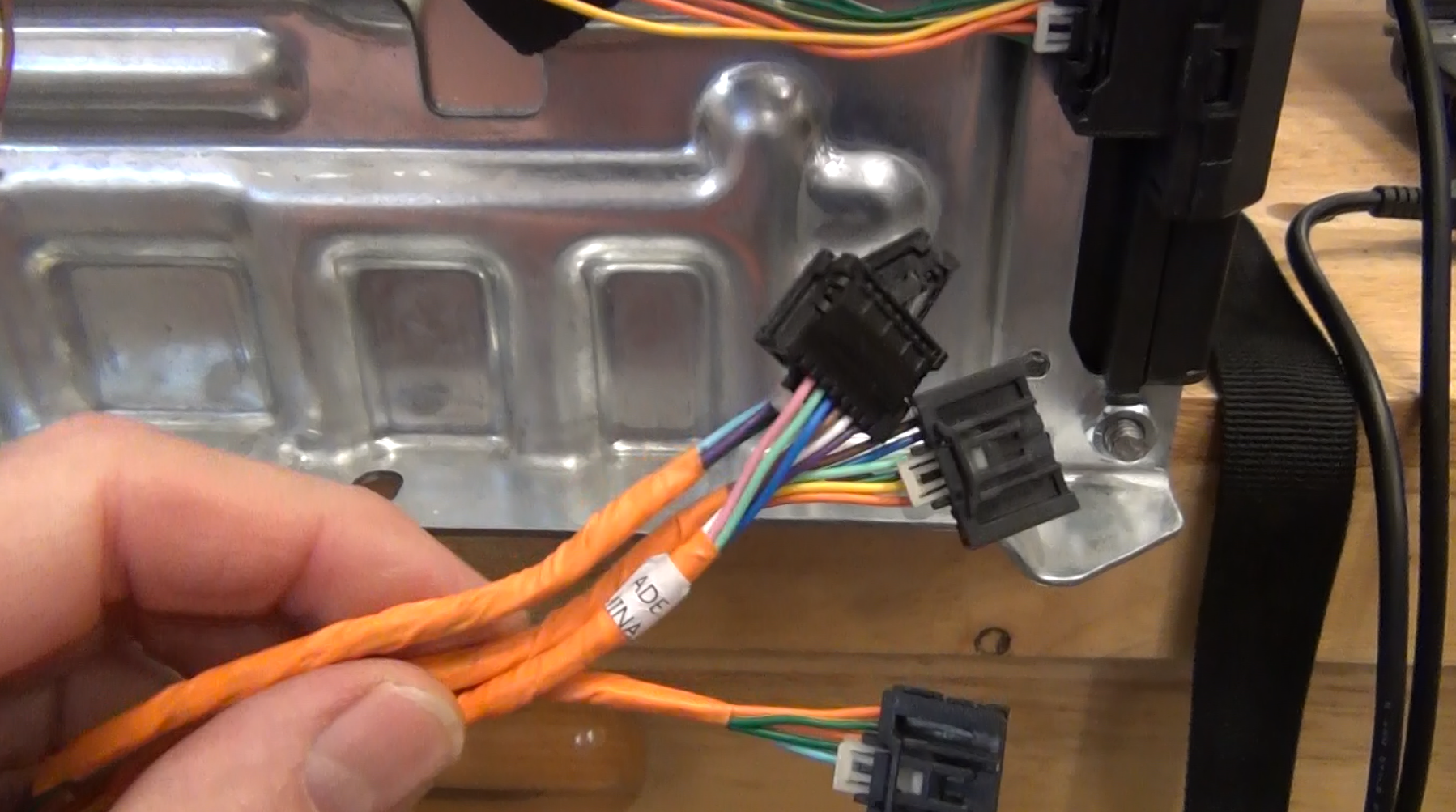
Two connectors are required to connect to all the battery cells in the module. A DB25 connector is used for the wires coming from the battery module to make connection the BMS demo board.
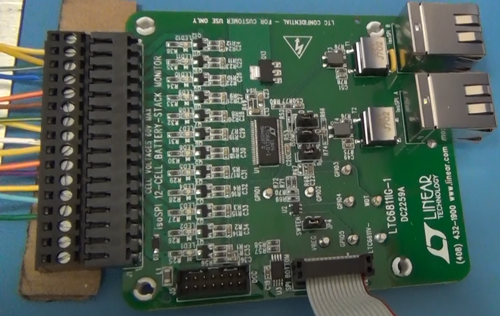
DC2259A BMS demo board that demonstrates the LTC6811-1 BMS integrated circuit.
Bolt Battery Monitoring
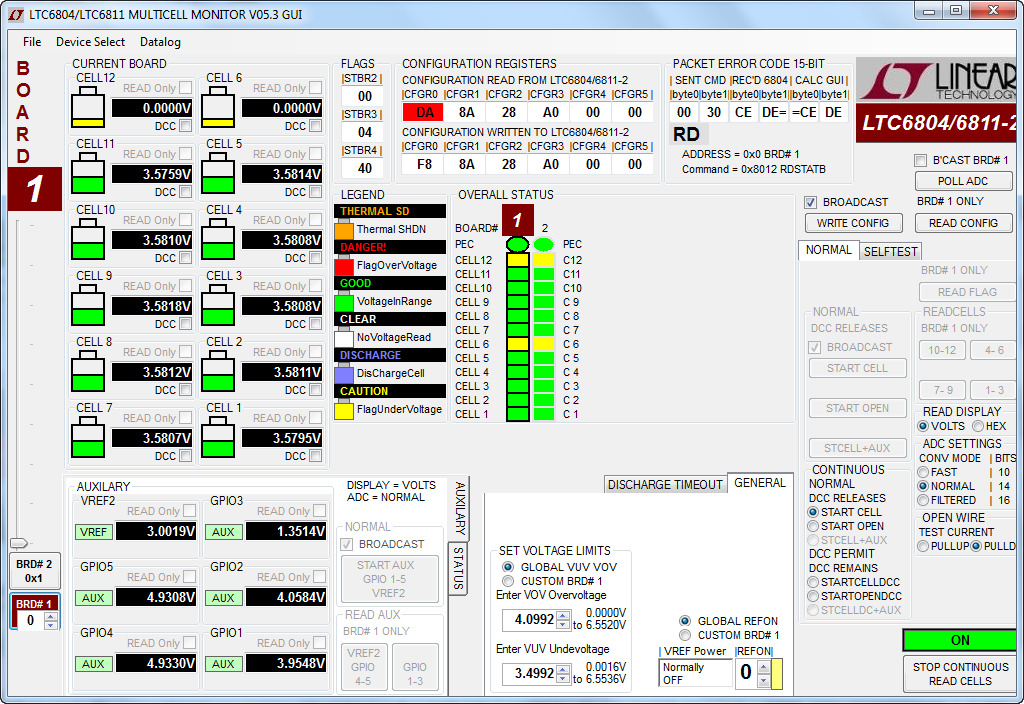
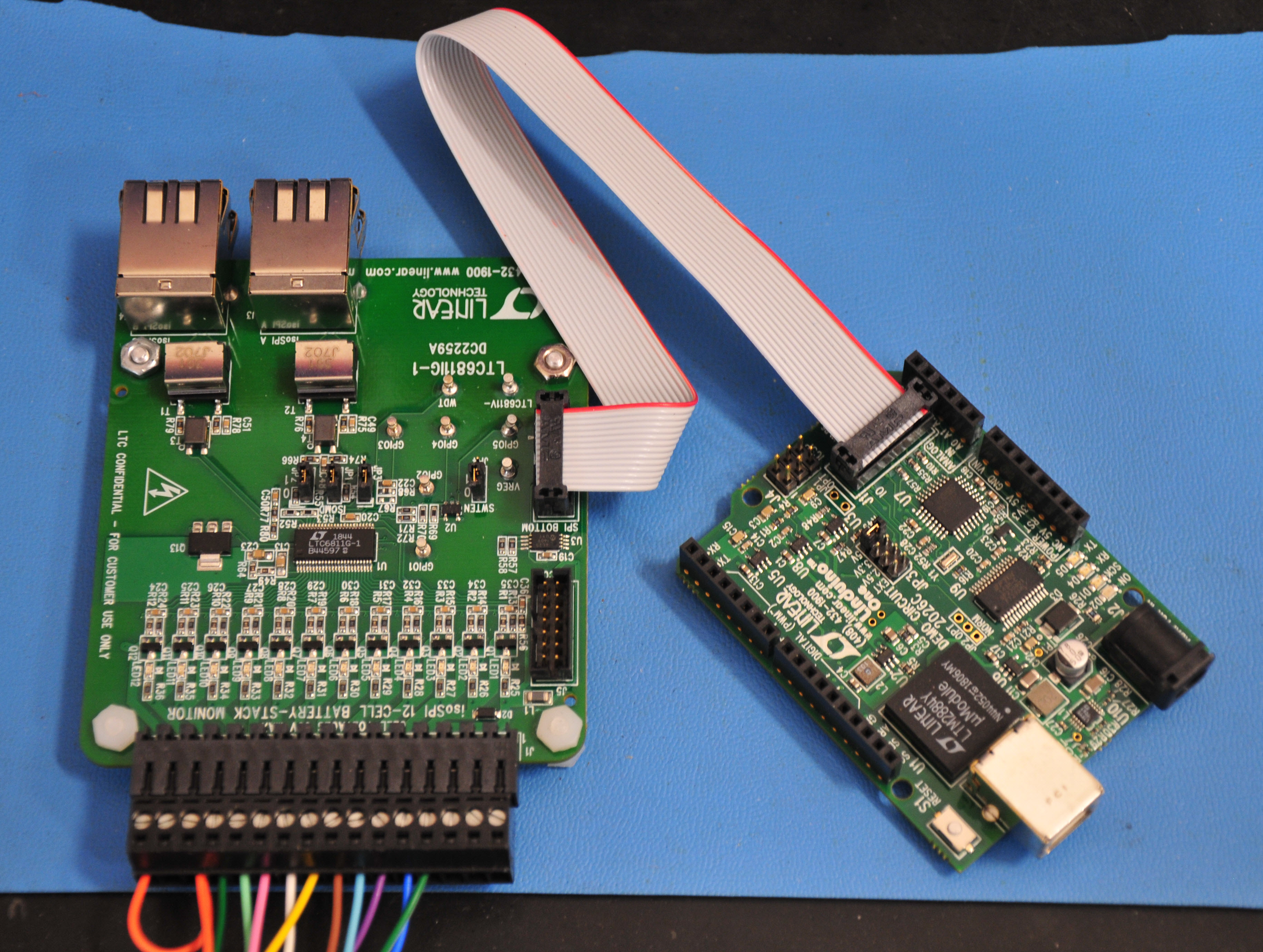
With the use of the Bolt Battery there is no need to bottom balance the cells within the module. The batteries come from the factory perfectly balanced and the way the cells are wired, individual cells are not likely to change voltage relative to other cells in the module. Below is a screen shot of the Multicell Monitor demo software that comes with the demo BMS board. The software displays the voltage of every cell. You can see the cells are all within +/-1mV of each other. A survey of the 9 Bolt Battery modules found all 90 cells to be within +/-2mV. The software also can turn on the tuning function, which can discharge each cell individually, if needed. The board has 12 channels to measure a mulitcell battery like the Bolt Battery. But on the Bolt Battery there are only 10 cells. To use the BMS demo board the 6th and 12th connections are shorted to the adjacent inputs. This is just a consequence to the internal wiring of the ADC. All of the functions and measurements shown on this GUI are available with an Arduino sketch that Analog Devices also supplies with the BMS demo board. Analog makes an Arduino board equivalent to the Arduino Uno board called the Linduino and a shield, DC2792B that has Isolated SPI (isoSPI) communication. Up to 5 BMS demo boards can be connected via the isoSPI. The Analog Devices web page with these boards can be found here. A look at that the BMS demo board with the Linduino is shown below the screen shot. The BMS demo board can be connected via the 14 pin ribbon cable to the Linduino for demo purposes, but the way the BMS demo boards will be connected in the car is with the RJ45 connectors on the end of the board that are for the isoSPI connection. See the section below on Battery Maintenance System for more details on the isoSPI connections.
Battery Maintenance System
Initially the Battery Maintenance System (BMS) will be provided by the Analog Devices DC2260A BMS Demo board which demonstrates the LTC6811-2 BMS integrated circuit. This circuit has the ability to measure 12 battery cells simultaneously and communicate via either isolated SPI or standard SPI. The demo board is connected to a Linduino with a 14-pin ribbon cable. The Lindunio is Analog Devices version of the Arduino Uno and is required to communicate to any Analog Devices demo board. Standard SPI is used to communicate with the Linduino. If multiple BMS Demo boards are used then the isoSPI interface is used and the Linduino needs a DC2792B shield. The D2260A demo boards are somewhat expensive ($150 +S&H) plus the cost of the Linduino ($125) and DC2292B ($75) shields (9 demo boards plus 2 Linduino and 2 DC2292B). Plus an overall controlling circuit needs to be designed to take the data from the Linduinos. A new circuit based on the DC2260A has been designed and the initial build started. The new circuit design incorporates an Arduino Nano processor and an isolated CAN BUS interface. The Nano communicates with the LTC6811-2 to read the cell voltages and then sends that data out on the CAN BUS. A much cheaper implementation and there already is a CAN BUS system in the car the controls the dashboard instruments. Probably the first 4 battery modules will be used with the DC2260A BMS demo boards and the other battery modules in the car will be monitored with my circuit design.
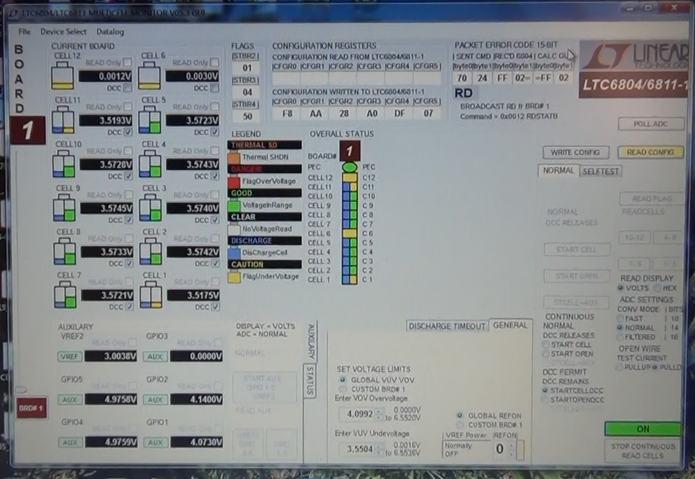
The screen picture below shows the Multicell Monitor GUI during the discharge process. In normal operation in the car, only cells that are at a higher voltage would be discharged. An algorithm will be written to control that process.
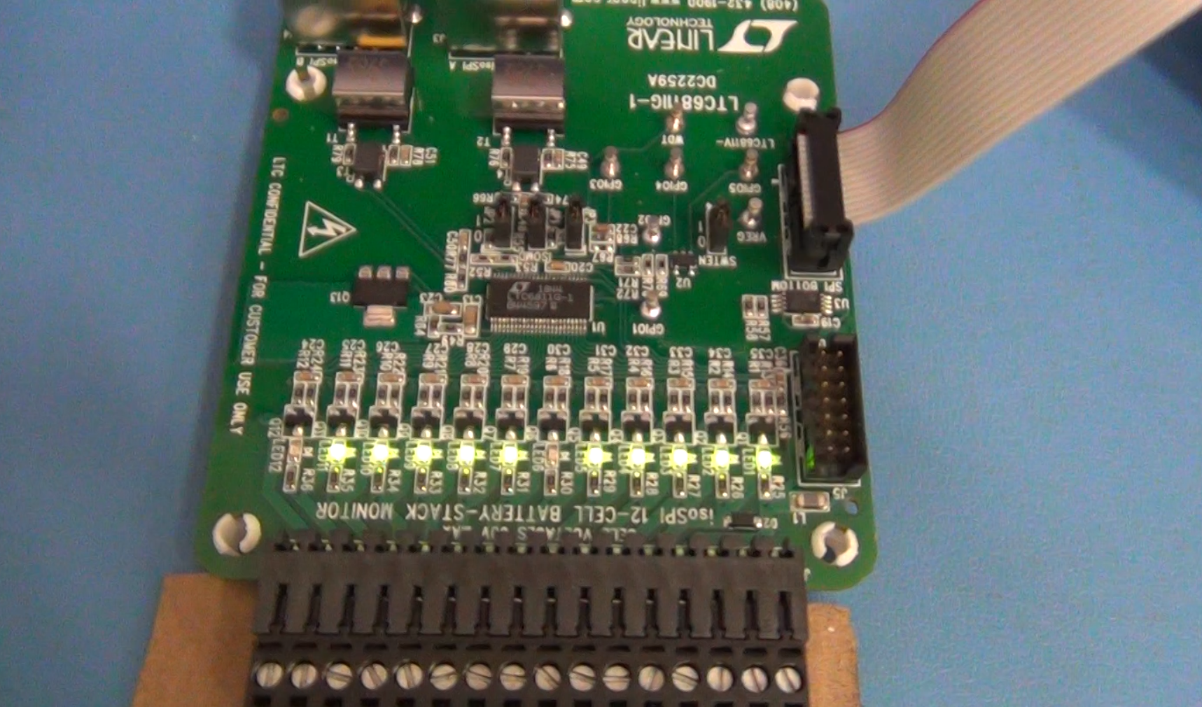
Top side of DC2259A BMS Demo board showing active discharge channels. When the MOSFETs are turned on to discharge a battery cell the LEDs light up. Again, 6 and 12 are not lit because they are not connected on the 10 cell battery module.
Bottom of DC2259A showing the discharge resistors. The resistors are 330 ohm so on a battery cell that varies from 3.5V to 4.1V there can only be a little more than 100mA discharge current. On a cell that is 180AH that would take a huge amount of time to fully discharge. This board is not designed for that. The design is to just trim the cell voltages so they are all the same value.
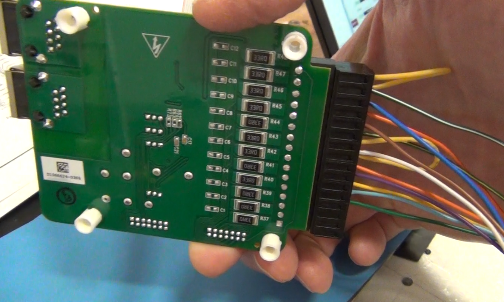
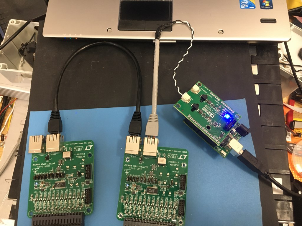
Image below shows the demonstration of the isolated SPI (isoSPI) that will be used to connect up to 5 BMS demo boards to one Linduino and a DC2792B isoSPI shield. In the car there will need to be two Linduino/DC2792B controllers for the 9 Bolt Battery modules. With the other BMS demo board shown above, the DC2259A, the board can only connect multiple boards by daisy chain SPI. Not as isolated as the isoSPI but more boards could be connected together. The iosSPI is limited to 5 boards and requires the addition DC2792B shield. The daisy chain SPI can connect more boards and does not require the shield.
Charging Sysytem
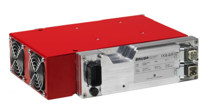
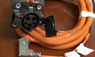
A Brusa charger is used to charge the batteries. This charger has a CAN Bus control interface so it is possible to setup the charger with the CAN Bus that is also used to control the instrument cluster. Usually the charger only has to be setup for a constant current setpoint voltage and a constant voltage setpoint. The charger is designed to handle the control of the current and automatically complete the charge. The charger is connect to the charging station via a J1772 connector and plug. Below is the charger and below that the J1772 connector and cable. The silver connector goes to the Brusa.
Siemens Electric Motor and DMOC 645 inverter (DMOC currently not used on car)
These components came from the liquidation auction of a company called Azure Dynamics in Nov. 2012. AZD was involved with converting Ford Transit Connect service vans into electric drive vehicles. Unfortunately they went bankrupt and had to auction off all of their assets. The late Jack Rickard of EVTV Motor Werks picked up a number of the motor/inverter combinations in the auction. The Siemens 1PV5135-4WS14 motor is a AC induction motor capable of generating 225 ft-lb of torque. It is a high voltage motor that requires over 300V for operation. The DMOC 645 inverter is a AZD design and is rated at 118kw peak power. The inverter has no control function in it. The AZD design intended to use a Vehicle Control Unit (VCU) to control the DMOC and the vehicle. Unfortunately the VCU and code were not available at the auction. The lack of a VCU to control the DMOC prompted Jack Rickard to generate a specification for a General Vehicle Control Unit (GEVCU). See the article on the GEVCU.