BMS Deployment
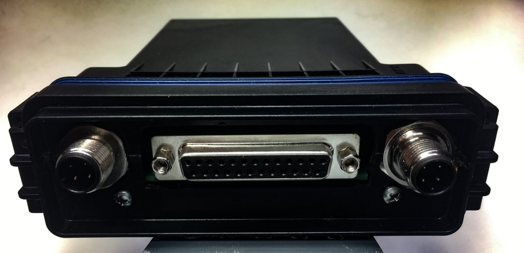
Now that I have most of the BMS PCAs completed it is time to plan for the deployment of the systems in my car. As I described below I plan top use a CINCH enclosure for the PCAs. The image below shows the enclosure with a prototype front panel. It was machined oversize to determine the best fit for the PCA in the enclosure and see how the 12mm circular connectors would fit. Now I have the measurements I can machine the front panel to fit the DB25 connector precisely. I will probably use some silicon sealer to seal the DB25 connector in the front panel to try and maintain the IP67 rating. Even though the BMS modules will be inside the car, the electronics can be affected by humidity. Originally I was planning to have two connectors with one an input and one an output and daisy-chain the BMS modules together. But I realized after I drew up the connection plan that it would mean the 12V power would be in series with each BMS. It would be better to have the 12V power connected in parallel. The CAN BUS can work either way, daisy-chained or terminated.
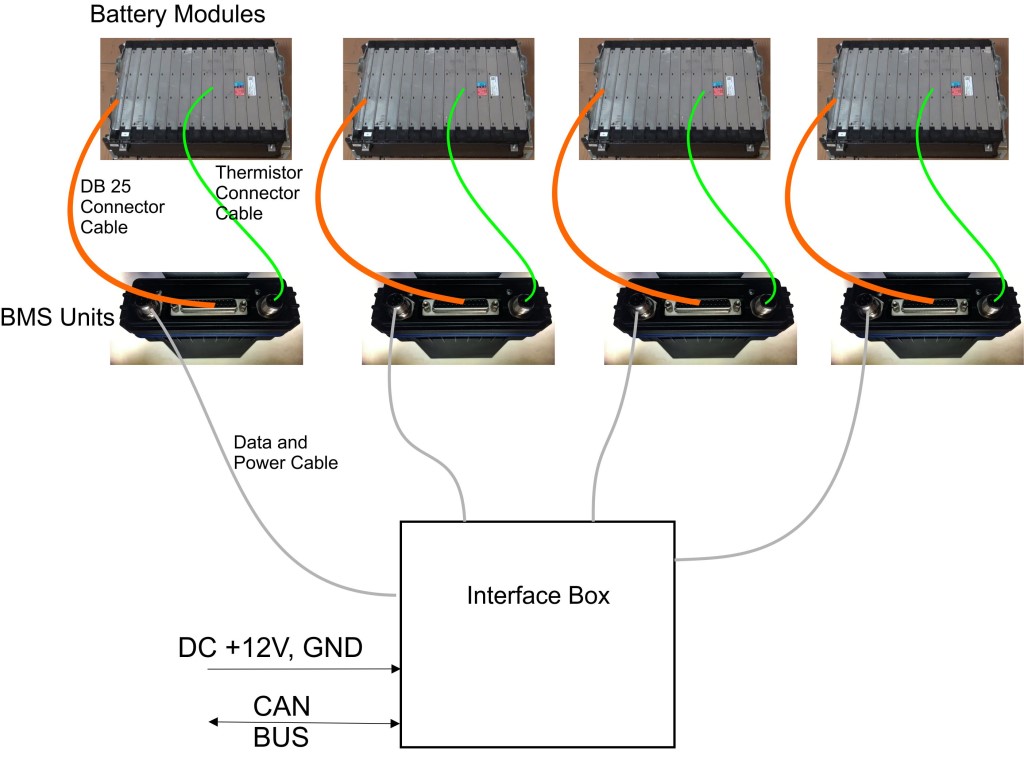
I decided to use only one 12mm 4-pin connector and have the CAN BUS be distributed to the BMS modules via the Interface Box, shown in the image below. The interface box will connect all the BMS systems together. The interface box will supply the +12V power and the CAN BUS communication and inside the box will essentially just be a busbar for the +12V and CAN BUS, no electronics required. Since I have 4 batteries under the rear seats and 4 batteries in the trunk there will be two interface boxes. The interface boxes will connect with one cable to my instrument cluster controller to read the CAN BUS. I will use the same 12mm circular connectors on the interface boxes. I ordered some 4-conductor shielded cable so now I just need to order all the 12mm connectors. After I realized that I was not going to use two connectors to connect the power and CAN BUS I was thinking it might be good to use the second connector to have a few temperature measurements of each battery. The LTC6811-2 that is the BMS integrated circuit in addition to all the battery cell inputs has 4 auxiliary inputs that could be wired to the second connector and the wires would go to a temperature sensor mounted on the battery. The code is already available in the program for the BMS to read the voltages on those auxilary inputs.
Quick Update on the Deployment: A thermistor is not going to work for temperature measurement because I do not have a Wheatstone bridge circuit to measure the thermistor resistance and hence the temperature accurately. That would require a respin of the PCB to include that circuitry. One solution for temperature measurement is to use the Analog Devices TMP37 analog temperature sensor.(Link) which is a one-wire sensor that just needs power and ground. Using this sensor I can get two temperature measurements per battery with the 4-wire cable I have. The sensor has a sensitivity of 20mV/C and a 500mV output at 25C, well within the range of the LTC6811-2.