BMS Battery Temperature Measurement
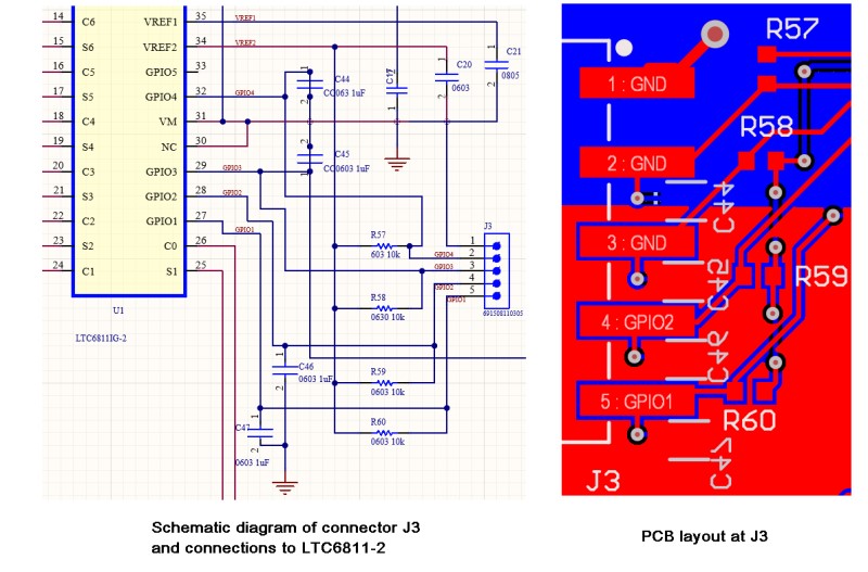
I thought I could use the four GPIO inputs on the LTC6811-2 for making temperature measurements on my battery modules. All four inputs reference the 3.3V source and the Analog Devices TMP37 work with 3.3V. However, I discovered that there is a mistake in the PCB layout that prevents me from doing that. For some reason all but the first two GPIO inputs are grounded. I reviewed the PCB layout and schematic and it appears that the changes I implemented in the schematic were not pushed to the PCB. See the image below. The schematic on the left shows all the pins on the output connector J3 are wired to the correct components and pins on the LTC6811-2. But that is not how the PCB layout looks, shown on the right. All the resistors and capacitors are there, just not the correct connections to the LTC6811-2. Unfortunately all the PCBs were fabricated with this error and all the PCAs have now been assembled.
This is a common problem I found with using the Altium CircuitMaker CAD program. Many aspects of the user interface of that program are very similar to Altium Designer, so it is easy for me to use because I was trained on Altium Designer, but because CircuitMaker is a freeware program it has a lot of bugs. Altium Designer is a $4235/year (or $355/month) program which I could only use when employed by my last job, where they had an Enterprise License. CircuitMaker is what Altium offers as a low cost solution to circuit and PCB design. I just wish they would charge something for it so it would have some technical support. With Altium Designer, tech support would usually reply within a day. Also, in Altium Designer there were many how-to demonstration videos on nearly any aspect of PCB layout and using Altium Designer. The only support for CircuitMaker is to post something in the CircuitMaker forum and then maybe a user will have a solution, but not likely. You can submit a bug report, but it does not mean the issue will be resolved. Most of the help can only be found by searching for it on the Allium site or YouTube. I also found that the layout problem is not the only issue. From a review of the documentation for the LTC6811-2 the VREF2 that is the 3.3V source can only source a few tenths of a milliamp so would it not work with multiple TMP37 sensors connected to the source. That is why in the design there are 10k resistors between the VREF2 and GPIO pins, they limit the 3.3V current. The circuit is actually designed for a NTC 10K thermistor. I tried to use that but with the GPIO pins shorted to ground it does not work to read a thermistor.
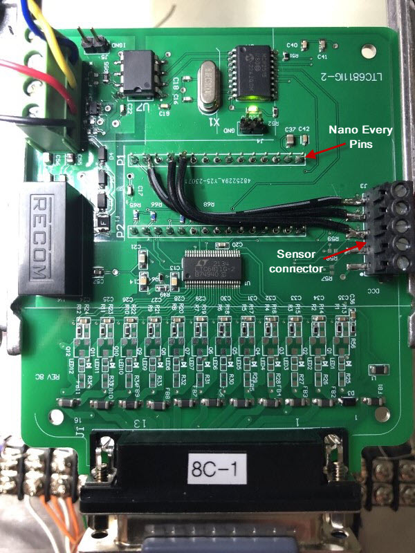
The solution I came up with is to use the analog inputs on the Arduino Nano Every, which is the controlling MCU for the BMS circuit. With the current BMS PCA design only the SPI and USB ports are used on the Nano. It has a full complement of analog, digital and PWM I/O. All the pins are available on the PCA because the Nano Every module is soldered directly to the BMS PCA and the module is on the bottom side of the PCA, so the pins protrude to the top side. Unfortunately to use the PCAs with this layout error, the traces from the pads for the the 5-pin sensor connector have to be cut to isolate them from the LTC6811-2 GPIO inputs or the ground connection. Since the connector that was chosen for the sensor connection has 5 pins I am going to just use two pins for analog input from two TMP37 sensors. One pin will be the +3.3V voltage source and one will be analog ground. This change will require three wires to be soldered to the pins on the Nano Every and to the 5-pin sensor connector pads. Using ribbon cable makes a cleaner look as shown in the image below. Once the boards are flux cleaned, I will probably put a dab of RTV silicon on the ribbon cable to stabilize it.