BMS Readout Prototype
I realized after I deployed the first four of the BMS modules on my batteries that the only way I could read and record the cell voltages was with a laptop computer, which was also how I could only measure the cell voltages with the Demo BMS that I started with (see Blog below Battery Maintenance System). Now because of the CAN BUS I can read and record all four batteries and eventually all nine with just one connection. However, using a computer is not always possible and also difficult to impossible to use while driving. I decided to make a system that could readout and record all the battery cell voltages, that could be connected to the batteries and operated at any time, or provide measurement and storage while driving the car. The readout system would need a display, a storage system and a Real Time Clock (RTC) to provide a timestamp for the cell measurement. All three of those functions are easily accomplished with small, easy to program modules. A 4-digit, 7-segment LED display like I used for the instrument cluster could be used for the cell readout. For cell voltage storage a MicroSD memory card can be used. I have built several other systems with MicroSD card memory modules and they are very easy to write and read from, usually with a SPI interface. The RTC is a standard module that again I have used in many other projects. The only other component required is some type of switch system to switch the measurements from cell to cell and battery modules. I found by searching that a rotary encoder switch would be ideal for the switching system. A rotary encoder continuously provides a count of the switch position, no matter which direction is rotated. Adafruit, an on-line electronic components vendor makes a small encoder with a I2C interface called the I2C Stemma QT Rotary Encoder (link).
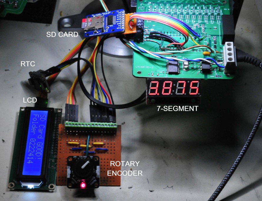
Since I have all of these modules, I decided to build a prototype to develop the code for the system. I will probably make a new PCB for this system because as you can see in the image below there are a lot of connections and wires that I had to add. For the prototype, I used the current design of the BMS PCA, but built one that had only the CAN BUS circuitry, the DC input and filtering and the Arduino Nano Every installed. I made a daughter board out of perfboard to provide additional connections. The modules either communicate with I2C or SPI or Serial. The Nano Every has connections for all of those communication methods. But the BMS board only has connections to the SPI buss. The 4-digit readout is perfect for displaying the cell voltage measurements as it will display to the millivolt, which is all that is needed to understand if cell voltages are changing. I have already determined the cell voltage is very repeatable and has a very small standard deviation well below one millivolt. The problem with the 4-digit is that it can only display numbers well, not letters. To get more information I decided to also add a 16 character by 2 lines LCD module. I did realize I could put the cell voltage measurement on the LCD and eliminate the 4-digit display. But I have found these kinds of LCD displays are hard to view off axis and usually cannot be seen with polarized sunglasses. The viewing angle issue is highlighted in the picture below. The 4-digit display is LED so it is viewable at any angle and with sunglasses. I will only use the LCD to display which battery the system is connected to and some information about the MicroSD card, like the folder where the data is stored. Below is an image of the BMS Readout system prototype. To record the battery cell voltages while driving I can automate the switching instead of using the encoder switch to select the cell to measure and store. The module labeled in the image below SD Card is actually a MicroSD card module that is another module offered by Adafruit (link). What is great about all of the Adafruit modules is that they always have links to code examples to drive the modules. That really makes the code development much easier. They also often have YouTube videos demonstrating the modules. Those were handy to see how the rotary encoders work.