BMS Readout Deployment
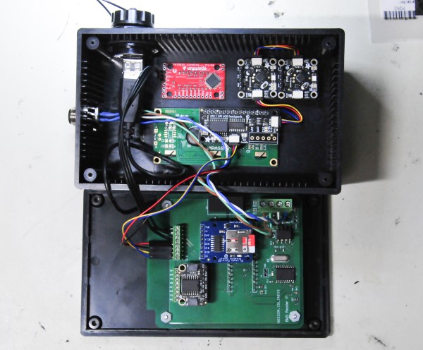
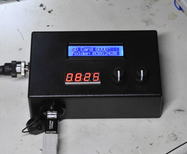
I designed an updated version of the BMS PCB, one that has connections to handle all the modules that are part of this system. During the time I waiting for the PCB to be fabricated I realized that all the Adafruit modules could be connected with the Stemma QT/Qwiic connector system. These are a connector specifically for I2C communication. Just 4 wires, ground, +5v, SDA and SCL and they come preassembled in all kinds of configurations (link). Using this system, I reduced the number of wire connections to the PCA that were required. I connected the two rotary encoders and the LCD with the Stemma QT cables. On the new PCA by using the Stemma QT connector system I only need one 4-wire connection to the PCA. The enclosure for the BMS Reader is the same Jameco enclosure I am using for some of the BMS modules (see the blog below BMS Ready for Deployment). I machined the Jameco enclosure to fit the LCD, 7-segment display and the rotary switches. You can see the enclosure, PCA and all the connections inside the enclosure in the photos below. I now have two rotary encoders because I found that was easier in code to have one to select the cells in the battery and one to select the battery module to read. The enclosure has the same 12mm 4-pin connector that I have on all the BMS modules for power and CAN BUS. I also added a USB feedthrough because although, all the battery cell measurements will be saved on the MicroSD card, I will eventually want to get all the data into my computer. With the USB feedthrough I can do that without taking the enclosure apart, which is what I would have to do if I wanted to read the MicroSD card. It would have to be removed to be read by the computer.