- Details
Chevy Bolt Batteries
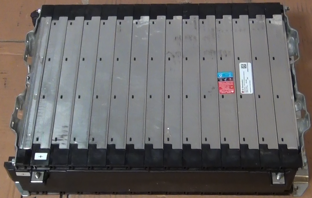
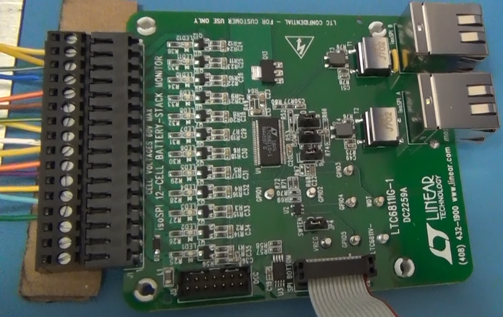
To get more driving range the batteries were upgraded in early 2021. The upgrade batteries used are the Chevy Bolt 5.94kW-h module shown in the picture below. These modules are made by LG Electronics and are NCM (Lithium Nickel Cobalt Manganese Oxide) chemistry. Each module has a 180AH capacity and the 9 modules that will be used gives a 53kW-h battery capacity. For a 85% discharge that provides 45kW-h of driving capacity. At the measured power consumption of 292W/mile by the vehicle that capacity should provide just about 155 miles driving range. A great feature of these modules is that they are already wired for a Battery Maintenance System (BMS). Each module has 10 cells wired in series and there are connections to each cell on the module so the individual battery voltages can be measured. The connections are a pair of multi-pin connectors at one end of the module. The Chevy Bolt uses a central processing unit for the battery maintenance so in the Bolt each battery module has a pair of cables that runs back to the central controller. For my build each battery module will have its own BMS controller. This is easier than running wires from each module up to the engine compartment. Although between the wires from one module the most voltage would be 41V (full charged battery) the wires will have the full pack voltage, with respect to ground. Local BMS control will be safer at this point in the 320e build. I was able to order the Chevy Bolt battery wiring harness on Chevy Parts Online. By taking the wiring harness apart I could build several cables with the corresponding connectors already attached and used them to connect to the local BMS controlling circuit. A BMS demo board, the DC2259B made by Analog Devices was initially tested to use for the module BMS. The connections to the battery module and a BMS demo board are shown in the second and third photos below. Although the new batteries are bigger and weigh more than the CALAB cells the new batteries will only increase the weight of the car 100 lbs but increase the driving range by 2 times!
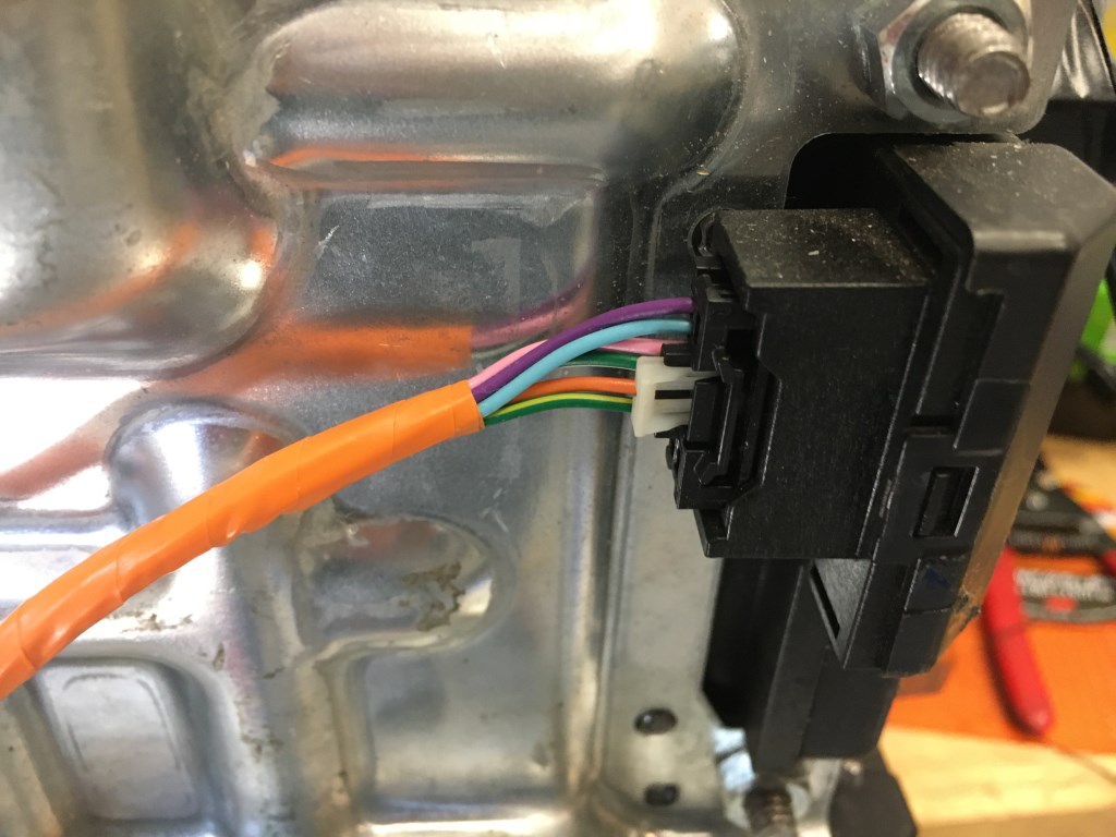
BMS connection on battery module. These connectors were obtain from a Chevy Bolt battery wiring harness that was purchased online.
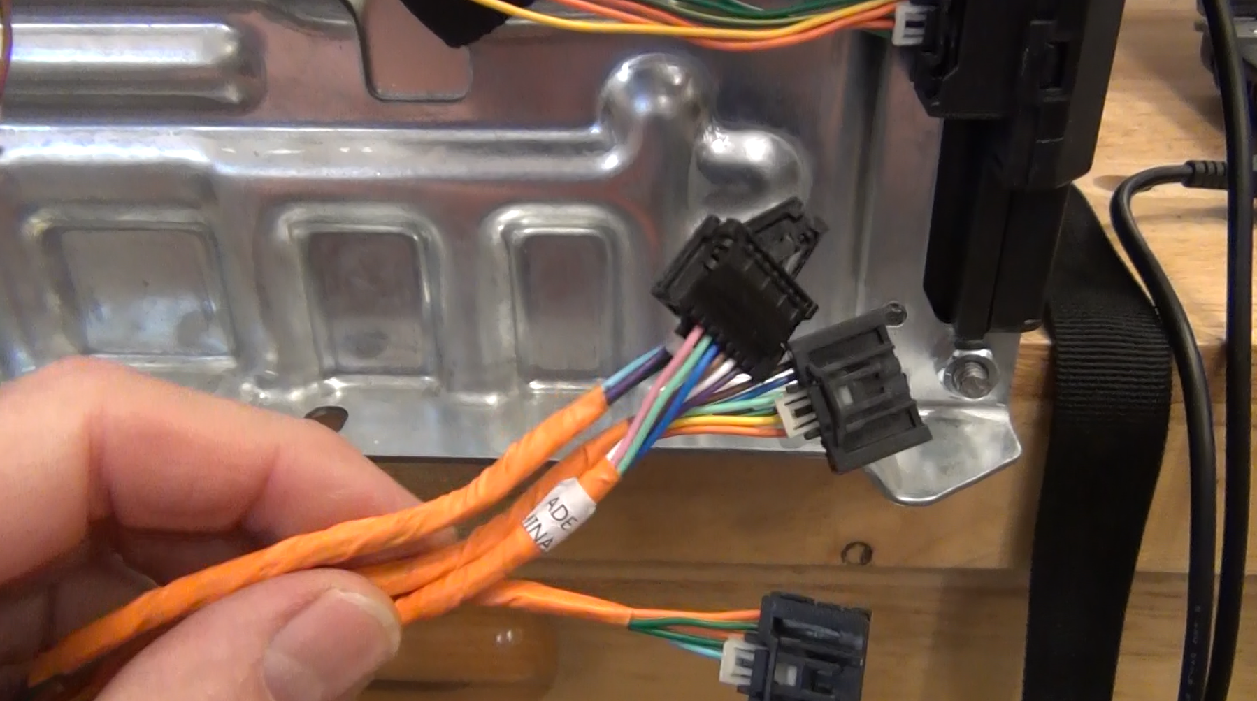
Two connectors are required to connect to all the battery cells in the module. A DB25 connector is used for the wires coming from the battery module to make connection the BMS demo board because the demo board is only supplied with screw connectors. The DB25 was installed to enable the test of all the batteries with one DC2259A Demo board.
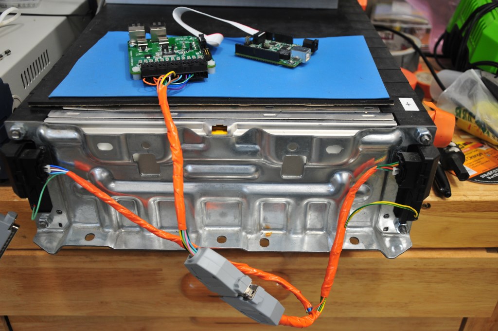
DC2259A BMS demo board that demonstrates the LTC6811-1 BMS integrated circuit. It is the 48-pin integrated circuit at the center of the board.
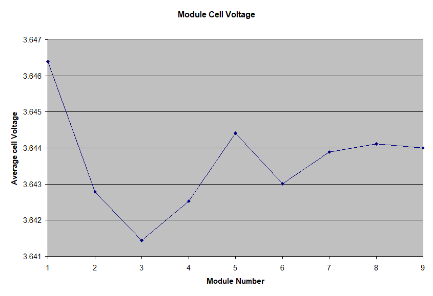
This is a plot of the average of the ten cells in each battery module that was measured with one DC2259A BMS demo board. This measurement is of the as-received modules from the factory. For effectively 90 cells the cell voltage variance is only +/- 2.5mV. If the two modules that show the largest difference we adjusted to match the other modules the variance would drop to +/- 1mV!
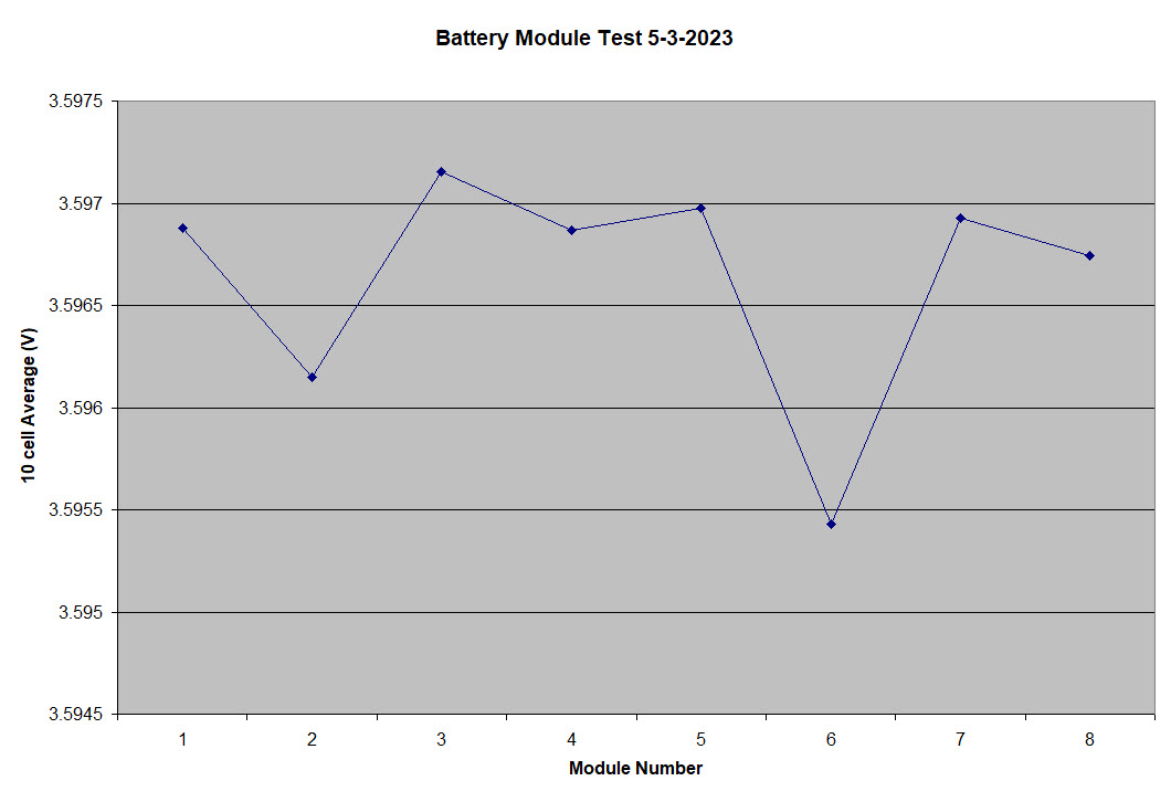
UPDATE: Below is the average cell voltage for 8 of the battery modules, measured recently. The batteries are at a different state of charge (SOC) but the cell voltage distribution is even tighter, less than +/- 1mV. The 9th battery module was not included because it is being used as a bench test platform and the battery box to house the module has not been built yet, so it is not in the car connected to the other battery modules. No adjustment of the individual battery modules was done. This is after nearly three years of charge and discharge cycles.
A video of the Chevy Bolt battery is coming soon.
Add a comment- Details
Scott Drive Installation
Although I was part of the group that originally developed the GEVCU to use with the DMOC so many years ago, I recently removed the GEVCU and DMOC and replaced them with a new inverter/controller called a Scott Drive. Even though I have been driving the 320e for nearly two years with the new tires and suspension I have had several problems with the GEVCU. The GEVCU would just suddenly fail to control. The symptom was all the calibration data was lost so the throttle and brake inputs would not register and thereby the car would not move. Also the contactors sequencing was lost so when the car was turned on so all the contactors would close causing one to fuse closed because of the high inrush current. I had to build another contactor system and placed that in the trunk. It ran independently of the GEVCU and used an Arduino Uno to control the sequencing and the timing of the contactors. I also had to jumper around my original contactor box. The GEVCU failure happened twice over the past two years and when it happened again recently I decided to replace the whole system. I emailed several other GEVCU users and some had seen similar failures. The consensus is that the EEPROM was failing – that is where the calibration and setup data is stored. That is very weird because the EEPROM is on the isolated side of the GEVCU board with the CortexM3 processor and no one saw a processor failure. It could be that I just got a bad group of EEPROM ICs. All the GEVCU boards I had were fabricated around the same time. But that does not seem like it could be the issue since others have experienced GEVCUs that were not built by me. All of the failures I experienced happened when the car was first turned on – I never experienced a failure while driving. Fortunately I was never stranded anywhere, the failures all occurred in my driveway or garage. The GEVCU failing was not the biggest issue, however. The fusing of the contactor was a serious problem because when the car was turned off it really was not off. The battery pack was still connected and that caused the battery pack to over discharge. This now made the third time the CALB batteries were discharged below 2.5V (see blog Driving soon???). Once I recovered the batteries I found several that would charge to the upper voltage limit faster than other batteries, even though they were all bottom balanced to the same voltage. That became a problem because the pack charging would have to stop and I would have less than 60AH charge in the pack. I tested several of the high voltage batteries on the battery cycling system I have and they only showed a small decrease in capacity, anywhere from 5 to 8 AH. But I was seeing batteries max out and limit the total pack charge to 45AH.
I had purchased the Scott Drive SD100 from EV West more than 5 years ago thinking at some point I would do the upgrade. Of course the Scott Drive upgrade was not without problems. The wiring harness had to be changed for the throttle and brake and the Scott Drive has a completely different connector that had to be assembled. When I first tried to turn the Scott Drive the motor would not turn smoothly. I discovered a bent pin in the Siemens motor connector that was one of the motor phase control pins. The pin must have been bent when I installed the new control cable for the Scott Drive. Once I fixed that I then found the motor would spin smoothly, but only in reverse. The Scott Drive has a great GUI for setup, calibration and control of the inverter. But what I discovered next was that the firmware in my Scott Drive was several revs old so the controlling GUI would not work, specifically to change the direction of the motor rotation. That required a firmware upgrade via an AnyDesk session with Scott Osborn, the maker of the Scott Drive, who lives in New Zealand. It took a couple of weeks to arrange the upgrade. I hope for any future upgrades I will be able to carry out the process because Scott charges for the upgrade and the time difference makes it challenging to communicate. One feature of the Scott Drive that I don’t remember setting a limit for in the GEVCU was the maximum output current. My original 60AH CALB batteries are capable of discharging at 10C. That would mean a max current rate of 600A. The Scott Driver 100 that I have is limited to 400A. The inverter is also limited to 150kW peak, which is more than the DMOC was rated for. With 400A and my pack voltage of 375V I would get to the 150kW peak, at least for a short time during acceleration. It is hard to say if the limit changed the acceleration capability of the car. I never really measured it by anything more precise than the seat of my pants. I had always planned to take the car to a dynamometer. Unfortunately the closest shop to me that had a dynamometer closed last year and all the others were far away. Driving a long distance to one is really not an option as the pack is discharged, the voltage drops, so the output power drops. But the real problem is just having the range to go there and back. With a pack charge of 45AH that means just under 50 total miles driving range. Probably the range would be way under 50 miles because some of the battery capacity would be used on the dynamometer.
The last upgrade I did was not really planned. During one of the times that the GEVCU failed I was moving the car in and out of the garage with an electric wench. To pull it out I would attach the wench to a tree at the end of the driveway and then to pull it back into the garage I have a bolt screwed into the concrete to attach the wench. Pulling out was no problem because the 320e has a tow hook on the rear of the car. But on the front there is none so I was pulling on the main cross-over. I think what happened when I was straightening the car the tow band slipped off the cross-over and slipped onto the steering rack, thereby pulling on the tie-rod connection. That must have pulled something out of alignment in the steering rack as the steering was locked, I could not turn the wheels. Because the car was not pointed straight I had the jack the front of the car with a floor jack and slowly pull it back into the garage. I ended up having to replace the steering rack. Fortunately remanufactured racks are still available for my car. The upgrade was the mounting bushings that mount the rack to the car. I upgraded to polyurethane bushings that should give the car more precise steering. Also fortunately there are several YouTube videos on how to install the steering rack on mine and similar model BMWs. But seeing how it was done and doing it turned out to be very far apart. I hope I will never have to do that again!
A video of all these upgrades can be seen here.
Add a comment- Details
Wheel, Tire and Suspension Upgrades
Now that the 320i has passed inspection and is drivable it is time to customize the car a bit. The first thing I did was buy 15" Alpina knock-off wheels. They are 15"x7" spoke rims and look very similar to the original wheels on the car. The knock-off meant that they cost less than $200 a wheel. Real Alpina wheels cost $1000 a wheel! The 13" wheels that came on the 320i really limited the number and type of tires available today because of the diameter and width. The new 15" wheels make many more tires available. I got tires for the 15" wheels that were the exact same circumference as the 13" wheels and tires. That was done so the speedometer would still be accurate. I found a website that calculates things like offset and circumference called Rims and Tires. I also got the 15" wheels to help the clearance issue with the rear disk brakes. When I did the upgrade to disk brakes in the rear the upgrade kit warned that the calipers might interfere with 13" wheels. I had ground down the contact points on the calipers but they still dragged a little bit. Now with 15" wheels there is plenty of room. Of course getting the new wheels on the car would not be so easy. The issue is the offset of the wheel. That determines how far in or out of the wheel well the wheel will sit once it is mounted on the hub. It is important that the offset is correct so the wheel does not interfere with the fender or the shock mounts. The offset for the 320i rear wheels is 13mm. Unfortunately the wheels I got came with 18mm offset. That meant I had to get 5mm wheel spacers to make up the difference. Many wheel spacers are available for the 320i from many manufactures, in the correct diameter, thickness and bolt pattern. However, installing the wheel spacers was not that easy. I found that the rear hubs on the 320i had a 2mm area that was not machined down to the 57.1mm hub diameter. That meant the spacer would interfere on that edge and not make flush contact with the rotor. I had to take the spacers to my local machine shop High Tech Machine and have them cut clearance for that larger diameter offset. I found after installing the wheels a few times that I needed to install threaded studs into the rear hubs. That made alighment of the spacer disk and mounting the wheel much easier.
The next upgrade was to get a new suspension setup with coil-over shocks. A company called Ground Control makes a set of coil-overs for the 320i. I wanted to change the suspension so I could adjust the ride height and make it even in all the corners. With the added weight of the batteries over the rear axel, the rear of the car squat a bit with the old springs and shocks. Unfortunately installing the coil-over system was not that simple. For the front wheels the Ground Control system uses a larger diameter strut tube than what came standard on the 320i. That meant the old strut tube had to be cut off the wheel spindles and a new one welded on. I could not do that work, but I found a company near me that specializes in restoring old BMWs and does that kind of shock work all the time. The company Vintage Sport and Restoration (VSR) has quite an operation going. Not only do they have a multiple bay area with car lifts, they also have a full machine shop, weld shop, a body shop and paint room. They took the wheel struts off, cut the strut tubes off and sent the wheel spindles to Ground Control. For some reason it took Ground Control a long time to turn the struts around. I thought the whole process would take a couple of weeks but the 320i was there for over a month. Even though VSR measured the weight of the car (same weight I measured) and measured the corner to ground heights, Ground Control sent the wrong springs for the rear setup. Too short and too low of spring rate. VSR had to order longer and stiffer springs to get the right ride height. The ride height is adjustable with the Ground Control system and I had them set the height lowered to about 1".
When I was driving the 320i to VSR I noticed that I had a vibration in the front end at 40 -50 mph. Even from the beginning first drives there never has been any vibration of any kind while driving at any speed. The only difference was the new wheels and tires. I doubted it was the wheels and thought maybe the car needed a wheel alignment. When I told the guys at VSR about that, they noticed the new Dunlop Direzza tires I got were mounted backwards on the wheels. High performance tires like that have a rotation direction, so the vibration was caused by the improper mounting. Of course the tires had to be remounted and spun balanced. The new tires really make the ride feel great, very positive tracking. But they do have a downside. Because they stick much better to the payment they really cut the battery mileage down - nearly 20% compared to the old wheels and tires. Even with that mileage reduction I will have plenty of range to use the car as a daily driver. While the 320i was at VSR they also corrected a problem with the driveshaft alignment and an issue with the calipers on the rear brakes. The driveshft issue required the front engine mounts to be lowered more than an inch. That mean the left side mount spacer block was removed and the right side replaced with a bushing. While at VSRt they thought I should refer to the car as the 320e for electric drive. The "I" at the end of the model number for BMW always meant fuel injection. No gas being injected in this car, although you could say electrons are being injected into the electric motor, but that might be a little too much for some people to understand. So I think from now on I will refer to the car as the 320e. Thank you VSR!
The last upgrade was not really and upgrade as much as a reconfiguration. I took the rear seat apart and removed the leather seating material from it. Using a template I made from cardboard I cut a piece of 3-inch high density upholstery foam to fit inside the leather seating material to sit on top of the battery box tops. The rear seat now fits much better over the battery boxes in the rear seat area. It still will not be possible for someone to sit there, but it looks much better and should support small weight like groceries. Related to the rear seat area I installed sound damping material in the side cavities, behind the lateral trim panels, in the back seat. The new tires make a lot more sound on the road so the sound damping is necessary. In fact the first time I drove the car with the new tires I though there was problem with the tires because with the electric drive, the car is very quiet. Of course a lot of the noise was from the tires being mounting the wrong way. After VSR remounted the tires the noise was reduced, but still louder on the highway than the other tires. The Direzza tire formulation is only for summer driving. They are not recommended for winter driving - probably get too hard in the cold. I might get a set of Michelin Energy Saver tires like I have on my Chevy Volt for winter use. I might also have to get another set of cheap wheels. Not that I am going to drive in the snow much, but when there is a nice clear day I would like to drive the car. In the winter around here they put a lot of salt on the roads and I don't want to ruin my new Alpina knock-offs.
The way the 320e drives with the new stiff suspension and new tires is very different than the way it drove before. Because of the heavy weight on the rear suspension the car would pitch a lot in turns and understeer. It also took bumps hard because most of the suspension was compressed with the heavy weight of the batteries. With the new setup the ride is a little bumpy on side streets but on the highway very smooth and very positive control. The car also corners really well now. Very happy with the upgrades!
A video with these upgrades and other upgrades can be seen here.
Add a comment- Details
Vehicle Inspection, Finally
A lot has happened in the year since my last post. To make room for all the cars at the house, I had a new two car garage built last fall. I also had a car lift installed in the new garage to make working on the 320i and others easier and the lift can be used to store a car during the winter months. I also got married and went on a honeymoon to Hawaii. So the 320i has not been worked on very much. To get the 320i ready to be a daily driver I did have to do some major work on the brakes. I could never get the power brakes to work and finally traced that to the vacuum boost cylinder. I had very difficult time finding a replacement. All of the units I could find were used and in very bad shape - worse than the one I had. The vacuum boost cylinder is not available from BMW or any part seller. Fortunately was very lucky to find a new unit on eBay. Someone must have been holding on to that for 35 years. They sold it for the same price RealOEM listed as the price when the part was available from BMW. Of course, replacing that vacuum booster required removing the master cylinder and then bleeding the brake lines. I have gotten really good at bleeding the brake lines with the pressure bleeder. After completing the work and running the vacuum pump I was able to get power assisted braking. Getting good working brakes was a major requirement for getting the car inspected. As I have said many times in several past blogs the 320i has to pass Massachusetts vehicle inspection before it can be a daily driver. What they really look at closely on an old car like this is all the mechanical aspects like body, tires, lights and brakes. They really have no inspection for the electrical drive so that should be no issue. It has taken nearly a year to get everything on the 320i fixed to the level needed to pass inspection. The last few things have taken months to complete, mostly because I only work on the car on the weekends. The windshield washers are a good example. Part of the engine compartment renovation I did was to replace the windshield washer reservoir. The old one was yellow with age and blue stained from the washer fluid. I could not find the exact part from RealOEM to replace it but found the 1985 320i washer reservoir was available and I ordered it. The problem is that BMW changed the pump motor design that year. The reservoir was roughly the same shape and mounted to the car the same way but the pump mounted differently. On my old reservoir the pump actually was inserted into the reservoir through a sealing gland on the side of the reservoir to pick up the fluid. The newer pump is outside and connects to the reservoir with a hose connection. The problem with the hit and miss part availability from BMW on the part list on RealOEM is that the older style pump was available, but the newer version was not. So I had to figure out how to adapt the old style pump to the newer reservoir. I ended up having to make a small angle aluminum bracket to hold the pump and connected to the reservoir with a hose. Just working weekends this little project took me over a month to complete. I also replaced all the water lines in the process so now the windshield washer system looks brand new. But, the washers work too good. The pressure is so high from the new pump that most of the washer fluid goes over the windshield and lands on the roof of the car. Either a resitor on the pump circuit or a flow restrictor on the water lines will fix that.
Another activity to get the car ready for inspection that took weeks to complete was gluing down all the last bits of carpeting. I had installed and glued most of the carpet, but did not finish the rocker panels or the rear seat or some areas around the accelerator pedal and transmission tunnel. Of course gluing up the last of the carpeting took much longer than the main part of the carpet and I ran into problems. When I was manipulating the accelerator pedal to get it through the hole I had cut in the carpet to my horror it broke off the mount on the floor of the car. I guess 35 years of acceleration was too much for the old rubber. Fortunately a replacement accelerator pedal was available on RealOEM and I was able to install the new pedal and get that part of the carpeting glued. Another problem I had to take care of before inspection was the gear shift. Ever since I installed the motor and transmission a couple of years ago, the gear shift was not in the correct position. It shifts okay but is not centered and my hand would hit the dashboard when I shifted into reverse or 5th gear. It has a bracket inside the transmission tunnel that mounts on top of the transmission that was really hard to manipulate on my back under the car to mount correctly. Now that I have a car lift in my garage I was able to remove the driveshaft and then remove the gearshift mechanism. The 320i has a short shift setup and my original mistake was to reversed the gear shift lever. The lever has a 30-degree bend in it and needs to be oriented correctly for the gear shift to be centered. Once I installed that correctly I installed a new drive shaft and universal guibo.
Trying to save space and weight I had originally installed a small 10 A-h 12V battery in the engine compartment to power the contactor relays when the car is started. Once started the DC-DC converter would provide all the 12V DC power needed to operate the car. Unfortunately the small milliamp leakage in the 12V circuit when the car is off drains the 12V battery below 12V in only a few days. I was having to connect my battery charger to the 12V battery to get the car to start. To eliminate this problem I decided to make the 320i like modern BMWs and put the battery in the trunk. I could use a much larger battery, the only problem is I needed to run a battery cable from the trunk to the engine compartment. That required pulling up some of the carpeting that I had recently glued down. I got a 12V dry cell from Summit Racing for the replacement battery. It is a 44 A-h battery and being a dry cell it can be mounted in any position. That solved the battery draining issue. For long term storage I put a manual disconnect switch on the battery.
The final issue to fix before inspection was the horn. The horn had always worked and I had removed the fuse just so I would not blow the horn accidentally while I was working on the car (working with high voltage it is better not to be startled). I had removed the steering wheel several times to make working on the interior easier and had replaced it to do my first two drives. Sometime during all the steering wheel manipulation I manage to shear off the electrical pickup for the horn. The horn circuit still worked, but pressing the horn button on the steering wheel did not. Again fortunately the replacement part was shown to be available on RealOEM, and was available from several BMW part sellers. That is one cool things about RealOEM. Through the diagram view of all the parts of the car it is possible to get the exact number of the part sought. A Google search can then be done on the part number and if its available it will show up as new from several parts dealers and BMW dealers, or if not links to ads for used parts on EBay. Of course replacing the horn pickup was not that simple. The old one was riveted to the steering column end plate, so those rivets had to be drilled out and replaced with nuts and bolts.
Finally everything was ready on the car for inspection. All my preparation paid off and the inspection went through without an issue. The inspector really did not check a lot of things, seems like they checked more on my new cars I have taken there but they did test that the windshield washers worked. I have been going to the same inspection station for the past 3 years and have been telling the guy there about my project. He was really happy to see the car and very impressed with the work. Now the car has an inspection sticker. The last thing I did was to get the Massachusetts EV plate. Massachusetts is one of the few states to offer EV plates. They are a cool way to indicate you have an electric vehicle and helpful for first responders if you get into an accident. They will know its and electrical powered car and know not to cut any orange cables! Now with everything compete I started driving the 320i as my daily commuting driver.
A video of this fun can be found here.
Add a comment- Details
2nd Test Drive, the drive between houses
Working on the 320i unfortunately has taken a back seat to a lot of things going on in my life. The biggest of which is I sold the house I have lived in for the past 15 years and bought a new house. We started the house hunting process last fall and it seemed like every weekend until the snow started we were out looking at houses. Once the snow started I started my usual winter activity, skiing. We finally found the house we wanted and purchased it earlier this year. We had some renovations we wanted to make before we moved in and those took until May to be completed so we just moved into the new house last month. The garage still needs a lot of organization. I had to breakdown 3 years of all the systems, components and tools I had put together and have them moved to the new house. I am in the process of setting everything up. The only problem is the new house has a smaller basement, but larger bedrooms. I will have to setup part of my operation in one of the bedrooms that I will also use as an home office. The 320i is still in the garage at the old house and will have to be moved soon. I would love to drive it to the new house but the car has not been inspected. Massachusetts requires autos to be inspected every year. The 320i has not been inspected in three years so the inspection sticker is expired. For an old car like the 320i even if it had the ICE still in it they would not do an emission test. They mostly focus on the mechanical aspects of the car and for an old car they really look at everything. That is reason why the 320i does not have an current inspection sticker. Although it drives just fine there are still a couple of little things that need to be finished before it would pass inspection. All of those things could each take a weekend to complete. The vacuum power brakes are the biggest issue to resolve and were my biggest concern driving the car. I planned to drive the car early on a weekend day, so there would be less traffic.
First I had to charge the battery pack. For all the time since the first drive I was letting the pack sit at half charge. Every week or so I would turn the car on and spin the wheels for a couple of miles. That did not really take much out of the battery. I still was showing 35 amp hours out of 60. But before driving it on the road again I wanted to fully charge the pack. Even though the drive to the new house is only 16 miles, 4 of those miles are on the interstate and I wanted to get a good measure of the battery use. To start the charging I checked all the connections on the car and I turned it on to charge the 12V battery (from the DC/DC converter) to make sure all the relays would latch. I then plugged the Siemens EVSE into the 320i. I had a lot of problems with this EVSE - the first one I received would not even charge my Volt. The one now installed has been working for over a year charging my Volt every day and it worked the last time I charged the batteries on the 320i. But when I plugged it into the 320i, it initially came on but then shut off with an error. I repeated the connection an noticed the Brusa charger was also coming up with an error. Who was erroring out first? To find out I used the J1772 cable that I had connected a NEMA plug on the end so I could bypass the EVSE and directly connect the Brusa to the 240V source. When I did that the Brusa came right up so the Siemens must be the problem. I have one of those AVC2 modules installed for controlling the J1772 interface but the Siemens does not seem to work with that. I used the serial interface on the Brusa to monitor the charge and checked individual battery voltages. Everything appeared ok and I charged for three hours to put another 10KW into the battery pack. I checked every battery voltage and none deviated by more than 25mv so the batteries are still looking good. I took the car out for a spin around the neighborhood. The vacuum brakes still are not working and the vacuum pump runs a lot. Not as much as before, but after each brake application it runs for several minutes. I tested it and the reservoir starts to lose vacuum with just a small amount of pedal travel. The pedal has to move half way to the floor to get the car to stop so it completely depletes the reservoir. It might be possible the vacuum brake cylinder is not working or has a leak. That would be a pain to replace, the master cylinder would need to be removed, which means disconnecting the brake lines so the brake lines would require pressure bleeding again. The other problem is just finding a replacement vacuum brake cylinder. That part is not available from BMW or any auto parts online store. On eBay I found there are vacuum brake cylinders available for other early model BMWs so I ordered one to see if it would fit. It has to fit the master cylinder perfectly to work. The mounting bolts to the firewall could be modified it there is some discrepancy.
The day for the drive from Methuen to Andover could not have been better. Sunny and nice cool temperature for July. The drive went very well, even went on the interstate for a few miles. Very smooth and no vibrations. Just had to get use to the manual brakes, that will stop the car, but require some leg strength. I think on these old cars the brakes never worked like they do now. They did not stop on a dime and you had the anticipate stopping and giving enough room to brake. I started out driving in 3rd gear which gave really good pickup, but the motor/transmission really screamed a lot when the rpm got to above 3000. I will have to determine what is going on there. In forth gear the car drove very smooth, even on the highway at 65mph and 3500 rpm. When I finished the drive I checked the power usage. For the 14.5 mile drive the car used 4384W so that comes to 302W/mile which is a really good number and right on with the rule of thumb that the energy usage is the car weight divided by ten. The car weighs just over 2860 lbs and with me and a tool box another 185 lb for a total of 3045 lbs. With the full battery pack capacity of 27KW that would be 90 miles. But the full capacity would not be used often. Usually the 80% capacity of 21KW would give used which should give 70 miles range. That is a bit lower than my design goal of 100 miles. To get to that goal I would need over 30KW of battery capacity and that could only be achieved with the new CALIB CAM72 cells that are smaller and have more capacity. I cannot add more batteries as I am at the 400V limit of the inverter so I would have to replace the whole battery pack. That is not going to happen.
A video of this drive can be found here.
Add a comment