- Details
Battery Design Debacle
After reviewing the battery layout in the car I realized that I made a major mistake in the number of batteries. The DMOC/Siemens combination only works at 400V or less. The DMOC will permit charging to over 400V but will not run the motor until the voltage drops to that level. I had thought I could put cells together in a parallel connection to increase that capacity of the pack while keeping the pack voltage down. The problem is that all batteries would have to be connected together in parallel pairs to have a system that works. Having a subset of cells in parallel effectively makes larger capacity cells than the other cells in the system. So when all the cells discharge though running the car, the different capacity cells will discharge at a different rate. They will also charge a different rate. Having all cells in parallel pairs would drop the system voltage by a factor of two down to 246V which is too low for the DMOC and Siemens motor to operate. There is no room to increase the number of batteries by 40% to get the pack voltage up. My new plan is to use 118 or 120 batteries, all wired in series. That will give a charge voltage of 420V for the 120 cell system. When the charging voltage is removed, the pack voltage drops considerably. Also, when the DC-DC converter is connected there will be an additional drop in the pack voltage. I will have to experiment to see what the optimum battery number will be. The lower number has a couple of advantages. One, it reduces the weight of the battery pack by nearly 100 pounds and two, reduces the design constraint for the number of cells in the engine compartment. Unfortunately the reduced number of cells will reduce the driving range. The original driving range for the 141 cell pack was expected to be 100 miles. The new driving range will be 80 to 85 miles.
Add a comment- Details
Adapter Revelation
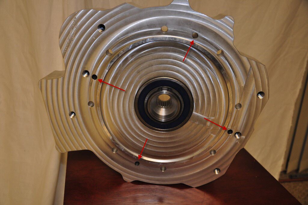
Part of the design for the engine compartment is fitting up the DMOC with the Siemens motor. I did not have a chance to place the DMOC in the engine bay when the motor and transmission where installed for the alignment and motor mount measurement. So while the engine and assembly is out waiting for an adapter solution I decided to see how the DMOC was going to sit on the Siemens in the way I had designed it i.e. with the DMOC parallel to the firewall. The DMOC will only fit in this orientation, because it is so wide. With the original placement of the motor and assembly the electrical connections for the motor would be on the side and there would be possible clearance issues with the hardware that is needed for the power brakes. Having the Siemens motor rotated 90 degrees puts the electrical connections on top where they would make the connections to the DMOC relatively easy. But as I have detailed below, the RebirthAuto adapter plate is not designed for that orientation. Just to see how the DMOC would fit with the motor I set the DMOC up on the motor with some wooden blocks (pictures). The motor in this orientation is actually rotated 180 degrees from the previous position. I realized in this orientation there would be plenty of room for the DMOC connection to the motor on the right side of the engine compartment. My revelation was when I placed the adapter plate up to the motor face and found it would work in this orientation. The Siemens motor has a alignment pin on the front face (photo). It turns out the RebirthAuto adapter is actually drilled for alignment in any of the 4 quadrants (photo). Someone had considered alignment in any of the 4 orientations, they just did not carry the idea far enough to provide connection to the Siemens bolt pattern in any of the 4 orientations. This means the adapter will work without any modifications. The Siemens motor in this 180 degree rotation only slightly impacts the design of the motor mounts.
Add a comment
- Details
Adapter Reject
I got the final word from ReBirthAuto today. They are refusing to take any action to remedy the issue with the adapter and feel they have met their obligation for what was ordered. I don't know how they can see that since they did not actually make an adapter for a 1983 BMW transmission and they did not account for motor rotation of the Siemens. The lowest cost option for me now is to take the Siemens motor apart and rotate the drive face. People that I know that have taken this motor apart do not know if the water cooling will be disturbed with the rotation of the drive face. I will not know until I take the motor apart. Look for a video of that adventure. If the face rotation cannot be done without disturbing the water cooling then I will have to look at a more costly option of machining a new adapter plate. I have already been in contact with a company that does 3-D scanning. Making my own adapter from scratch may end up costing as much as buying another one from ReBirithAuto, but then I would own the design and I will know it will be done correctly.
Add a comment- Details
Rotated Motor
Once I got the motor assembly out of the car I disconnected the transmission and the adapter. I rolled the motor over on its side so now the electrical connections are on top, which will make connecting to the DMOC much easier and make it possible to have the DMOC parallel to the firewall of the engine compartment. I started to align the adapter to motor in this orientation and discovered that the adapter was not made to permit this. The Siemens motor is not 90 degree symmetric so now the bolts holes for the motor do not line up with the holes in the adapter (pictures). With other motors like those from HPEVS the end plates of the motors are easily removed and rotated. But those motors are not IP67 sealed liket the Siemens (that means totally waterproof). It does not look like the Siemens is meant to be removed. So now I have a request into RebirthAuto to make a new adapter that will attach to the Siemens in this orientation. Will see what their response will be. If they are unwilling to make a new adapter I may look at making my own and use the spline adapter that is adapter plate. Unfortunately without having the CAD drawing for the adapter plate I fear making one from scratch will cost as much as the original one from RebirthAuto.
Add a comment
- Details
Transmissions Revealed
I got a response from RebirthAuto. They claim the correct adapter pattern was machined for my transmission. It seems there is some confusion on the 5-speed transmissions that were used in E21 BMWs in the early 80's. I have the transmission that is listed for a 1983 E21 5-speed, which is model number 240 manual transmission. From the pattern of the adapter that RebirthAuto provided it appears they patterned after model 245, another 5-speed transmission used in E21s. The problem is model 245 5-speed transmissions were only used up to 1982. Starting in 1983 and later BMW started selling cars with the model 240 5-speed manual transmission. The issue with the bolt pattern not lining up however, probably is a non-issue. I reviewed the video I shot during the removal of the ICE. Here is a picture that clearly shows the bottom of the engine was not connected to the transmission (because there is nothing there). There was a dust cover plate that was on the bottom of the transmission where the miss-alignment is with the adapter. So those bolts do not carry any of the transmission load. The remainder of the bolts that are connected should provide all the support needed for the adapter. So I will use this adapter as it is. The next step is to pull the motor and transmission assembly back out of the car so that the flywheel and clutch can be installed and the motor rotated 90 degrees. After these changes are made and once I have everything bolted back together I plan to spin the motor and transmission on the bench, before putting back in the car.
Add a comment